CP45-英文版培训教材.pdf - 第31页
Operating Manual MODEL Reference Figure CP-45/55 Operation Process Fig. 04. “ Parts” Dialogue Box Nozzle or Part in case that Nozzle and Part are mounted) during PCB works. In here, 8 mm re fers to the 2mm added value to…
Operating Manual
MODEL
Reference Figure
CP-45/55 Operation Process
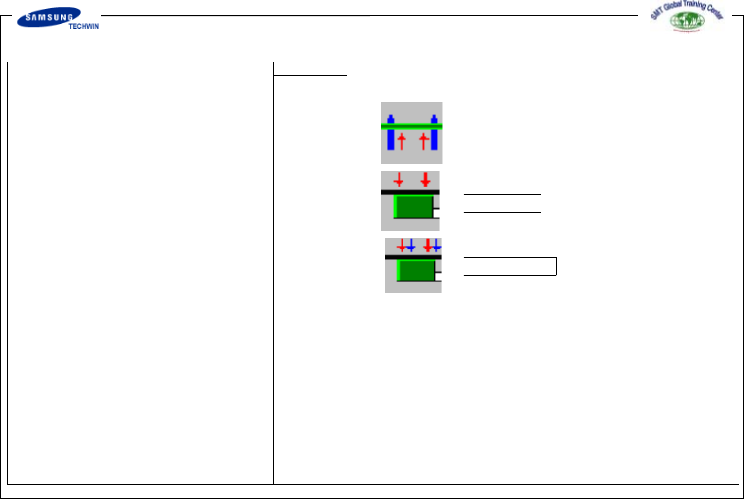
Hole Fixer
Edge Fixer
Edge Fixer2
^Holefixer
: To insert and fix Pin into a hole
of Board. Use this method when
there is no Board Fiducial Mark.
^EdgeFixer
:TopushandfixaBoardfromthe
side with a device equipped on
Conveyor. Use this method for
general Board with Fiducial Mark.
^ Edge Fixer2
: Same method as “Edge Fixer” but
push of two times.
v
<Wait Type> Combo Box
To select a wait position of Head
Block when Board Loading. Select
System in here.
-> Auto:Toselectwaitposition
to FD Mark1Position
automatically.
-> System:Towaitinpositiondefined
in System.
(System Setup / Head)
v <Move Z>
To select the min. clearance
between the top of PCB board
and the end of Head(Bottom of
Operating Manual
MODEL
Reference Figure
CP-45/55 Operation Process
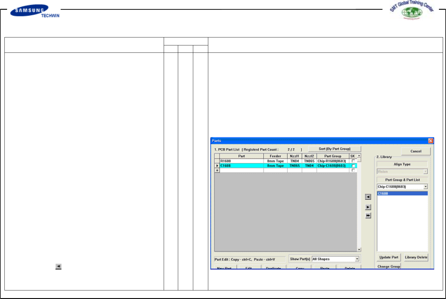
Fig. 04. “Parts” Dialogue Box
Nozzle or Part in case that Nozzle
and Part are mounted) during PCB
works.
In here, 8mm refers to the 2mm
added value to height(6mm) of
Conveyor Cover based upon the top
of fixed Board.
A height refers to a distance to the
bottom when part picked up. If
height of part mounted on Board
is higher than 8mm, input 2mm
added value to the height. Operate
it as it is except a case as like this.
v PCB IN Button
Click this button to input a Board.
3.2) Part (Work Part Register)
To register work part.
3.2-1)Library Part Use
(ChipR2012 100K)
Select Part what you want in
Part Group.
^ Select Part what you want in Group.
^ Click button to copy part
information to <1.PCB Part List>.
Operating Manual
MODEL
Reference Figure
CP-45/55 Operation Process
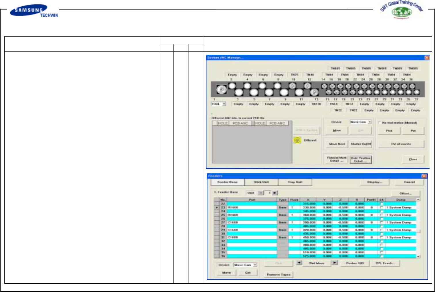
v ANC Setting
When placing a nozzle on ANC,
be sure to standardize and use it
as follows. Also, apply the same
placing method as the actual type.
Failing to observe this may cause
an error. If you change ANC Data
frequently, you may modify the Data
based upon PCB.
3.3) Feeder (Feeder Register)
3.3-1) Placing Feeder
Place Feeder by part on the optimized
position. After placement, be sure to check
the pickup position.
3.3-2) Test Pick & Part Align Test
Pick up the nozzle which is suitable to
a part on a head(Refer to ANC).
Execute Test Pickup by part and
check Align Data.