CP45-英文版培训教材.pdf - 第194页
Operating Manual Reference Figure CP-45/55 Operation Process 3.2 Difference Analysis 3.2.1 Difference of Tape Guide Fixing Part Problems : Locker is easy to open even re sponding to mi cro shock a s a result of poo r loc…
Operating Manual Reference Figure
CP-45/55 Operation Process
3.
Difference between The Existing
Feeder and Non Stop Tape
Feeder
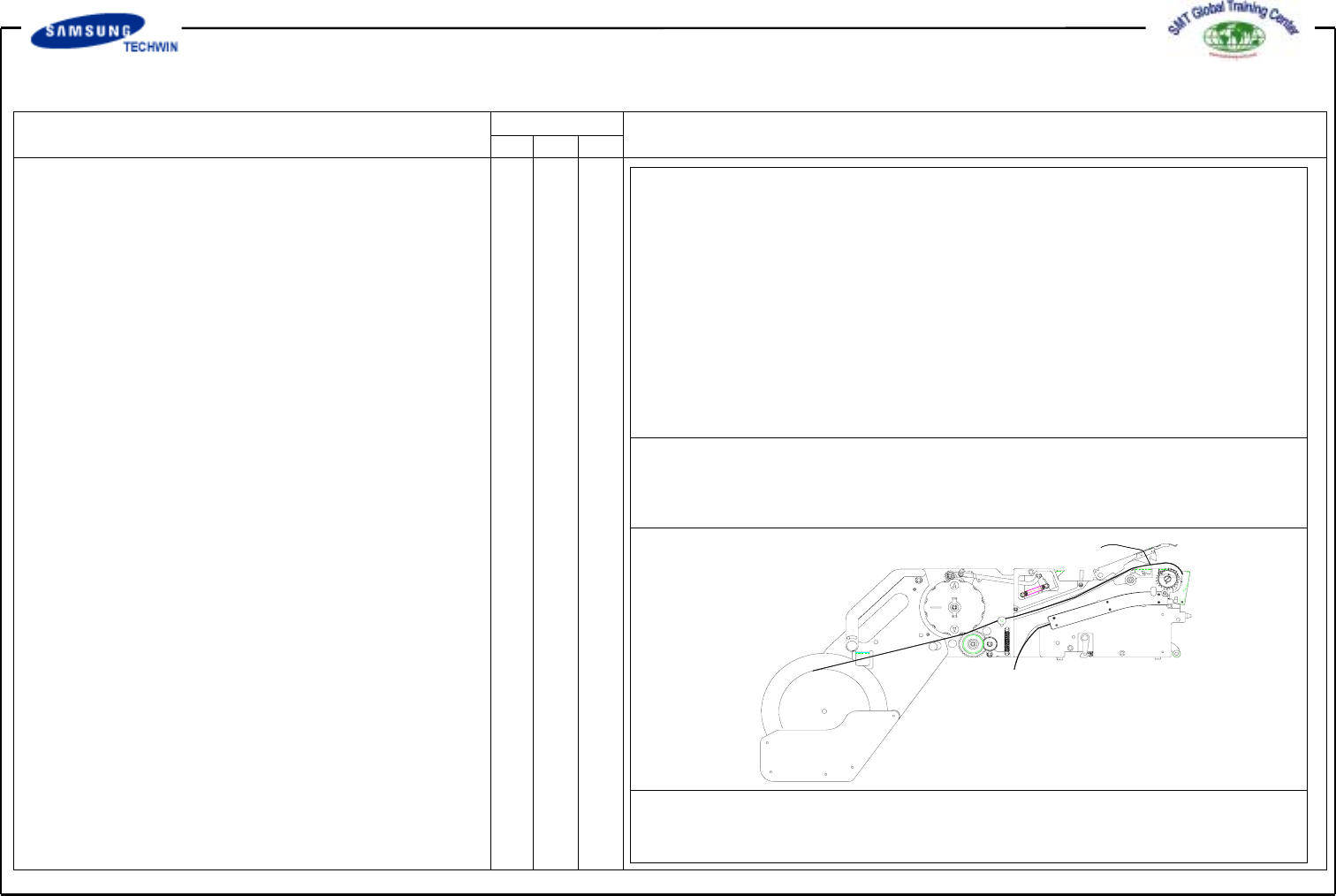
3.1 Development Drawing
Drain-type Tape Feeder
Non Stop Tape Feeder
Operating Manual Reference Figure
CP-45/55 Operation Process
3.2 Difference Analysis
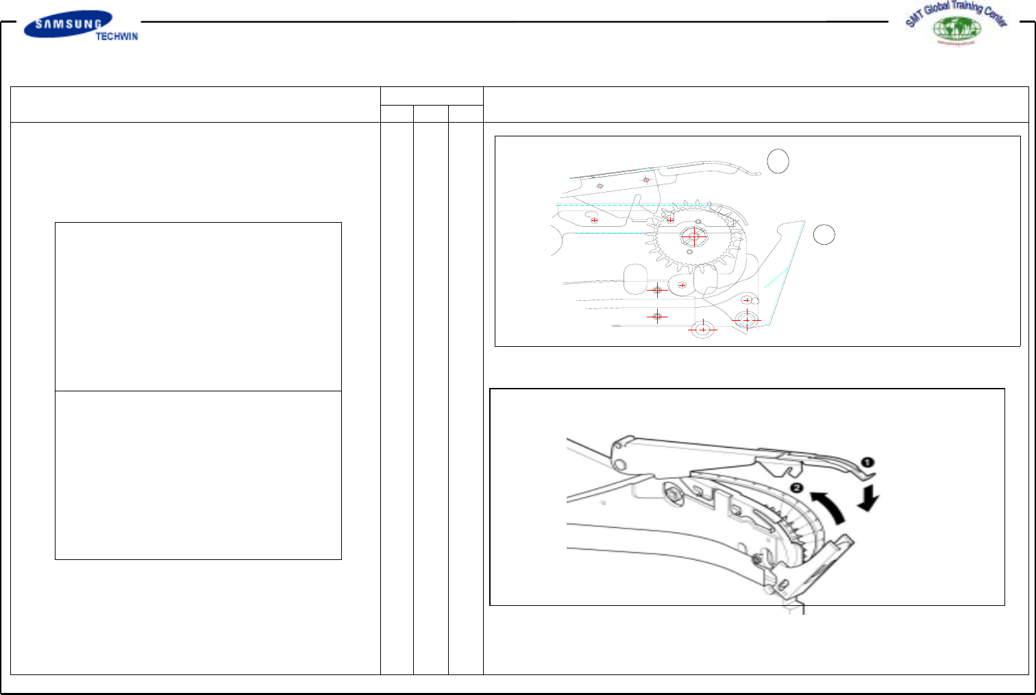
3.2.1 Difference of Tape Guide Fixing
Part
Problems : Locker is easy to open
even responding to micro
shock as a result of poor
locking caused by a shock of
a head and a feeder of the
chip mounter.
Problem of shock with Head was
improved.
It is judged that the locker will
not open during operation if once
locked.
1
2
Method of inserting No.1 tape guide into slot of No.2 locker
Method of clamping ends of No.1 tape guide with ends of No.2 locker
Operating Manual Reference Figure
CP-45/55 Operation Process
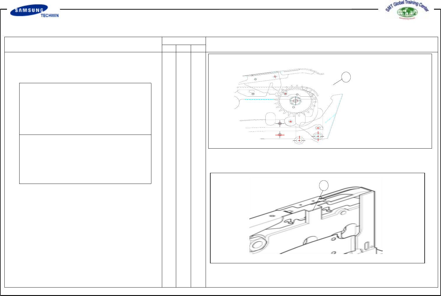
3.2.2 Difference of Feeder "Z Axis"
Control
1
1
*Problems : "Z Axis" set at the work
site can be deformed if temporary or
continuous shock occurs to No. 1
area of tape guide.
*-. It is structured in a manner that
post is put up on the main frame to
support the tape guide and drawn by
the locker.
"Z Axis" height is determined by tape guide.
"Z Axis" height is determined by main frame.