CP45-英文版培训教材.pdf - 第169页
Operating Manual Reference Figure CP-45/55 Operation Process 1.2.2. X-Y Frame Part 1.2.2.1 X-Axis L/M Guide Rail *Check Points* @Check the r ail for dust particles, or stain s, etc. @If the rail is dried too much, excess…
Operating Manual Reference Figure
CP-45/55 Operation Process
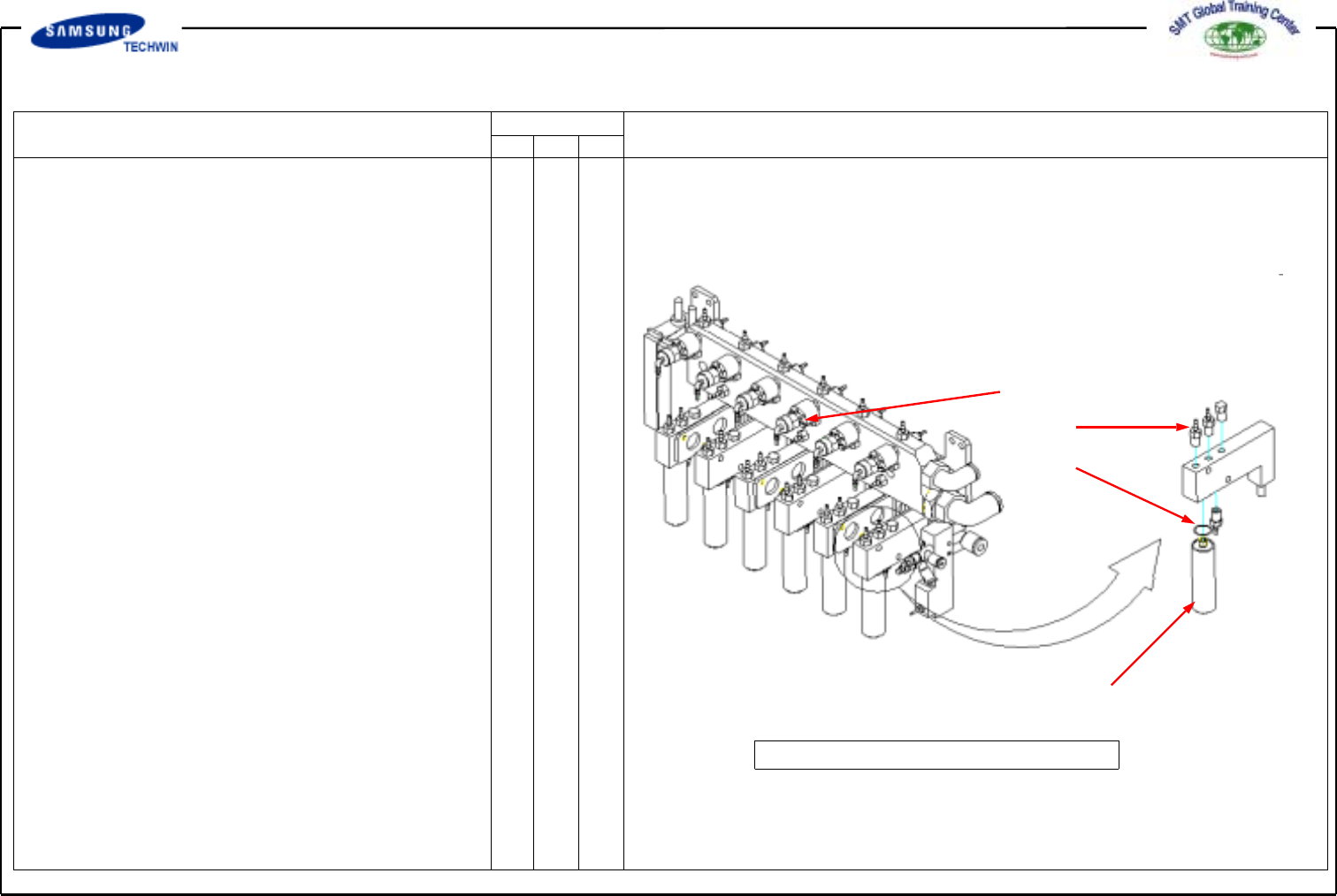
1.2.1.8 Air Part
*Check Points*
@Check the fittings of the air
distributor and the solenoid valve for
proper airtight.
@Check the blow chamber fitted on
the solenoid valve for proper
airtight.
*Actions to be taken*
@When the connector of fitting is
leaked, tighten it by suitable forces
so that the fitting can not be
damaged.
@If the blow chamber is loosened, air
leakage may occur to it. Tighten the
blow chamber for preventing from
the leakage. At this time, care is to
be taken for ensuring that O-ring in
the blow chamber can not be
missed.
@If replacing the part caused by
improper leakage or damage, be
sure to contact our designated
C/S company for proper actions.
air
DISTRIBUTE
fitting
O-ring
Blow chamber
Fig. 17. Vacuum Generator
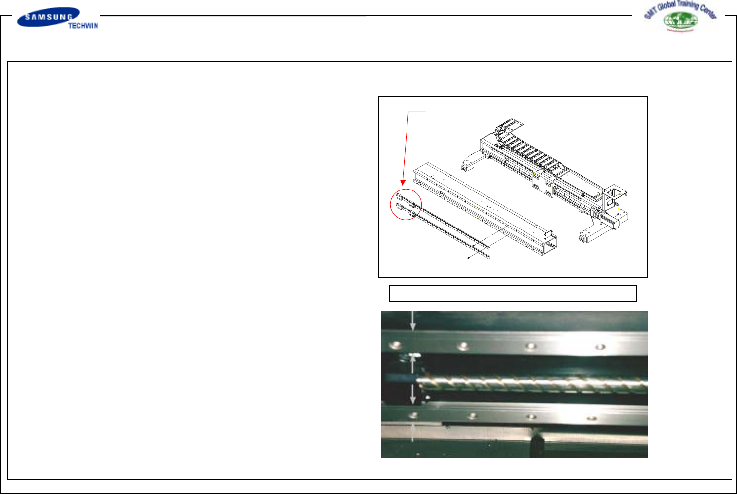
Operating Manual Reference Figure
CP-45/55 Operation Process
1.2.2. X-Y Frame Part
1.2.2.1 X-Axis L/M Guide Rail
*Check Points*
@Check the rail for dust particles,
or stains, etc.
@If the rail is dried too much,
excessive noise may occur. Check
the lubrication conditions.
X-axis L/M Guide Rail & Bloc
k
Fig. 1-8. X-Axis L/M Guide Rail & Block
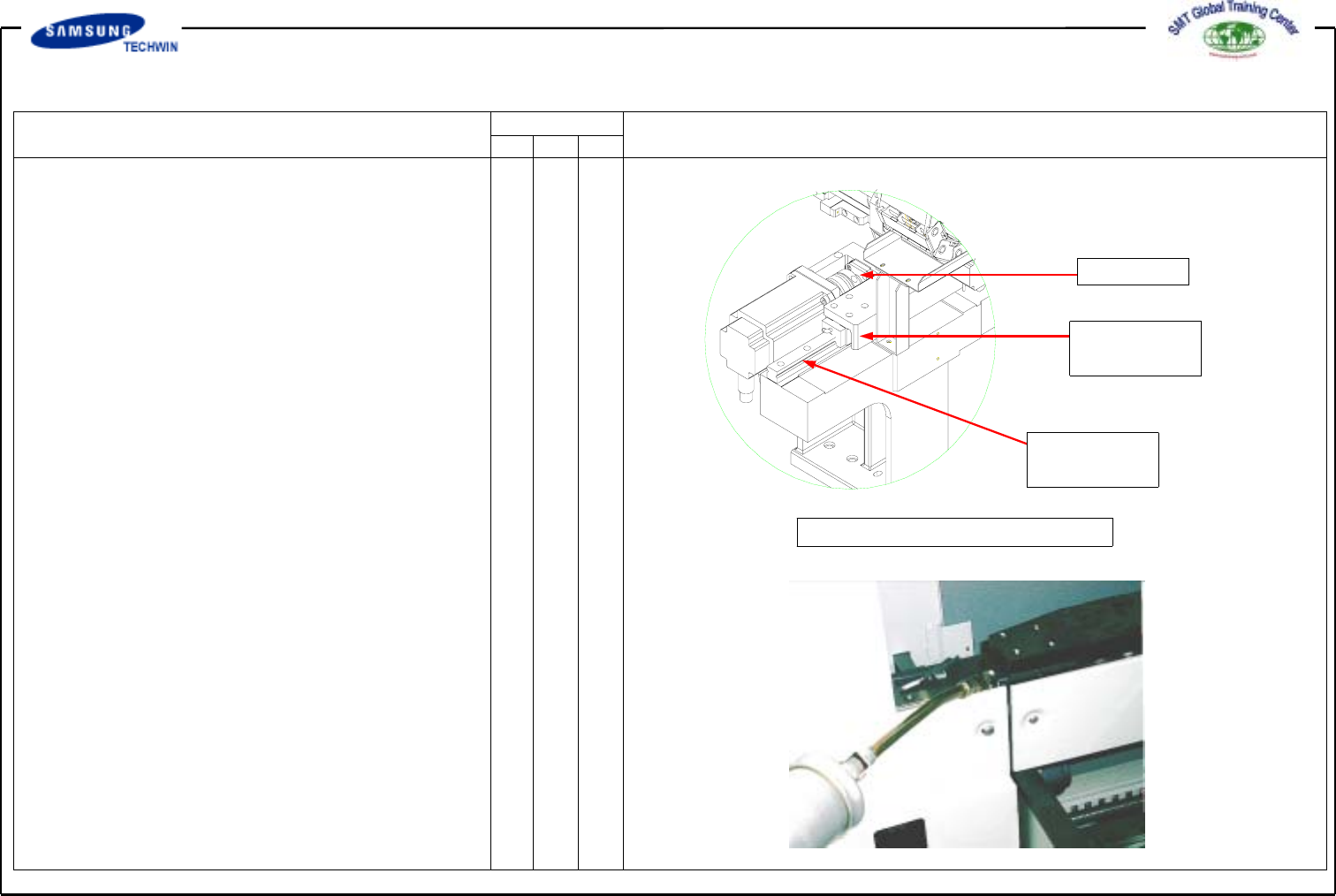
Operating Manual Reference Figure
CP-45/55 Operation Process
1.2.2.2 Y-Axis L/M Guide Rail
*Check Points*
@Check the rail for dust particles,
or stains, etc.
@If the rail is dried too much,
excessive noise may occur. Check
the lubrication conditions.
L/M Guide
Rail
L/M Guide
Block
Coupling
*Actions to be taken*
@Clean out dust particles or foreign
materials, etc. with dustproof cloth,
and, if required, apply thinly the
grease to the rail surface with a
brush.
@Refer to an Article 1.1.2 General
Lubrication for applying method.
Fig. 1-9. Y-Axis L/M Guide