CP45-英文版培训教材.pdf - 第198页
Operating Manual Reference Figure CP-45/55 Operation Process [M o n i t o r1f o rS p r o c k e t Inspection ] [M o n i t o r2f o rP o c k e t Inspection ] [ Line I ndicator ] [M a s t e rJ i g] 4. Adjustment of Regular P…
Operating Manual Reference Figure
CP-45/55 Operation Process
3.2.4
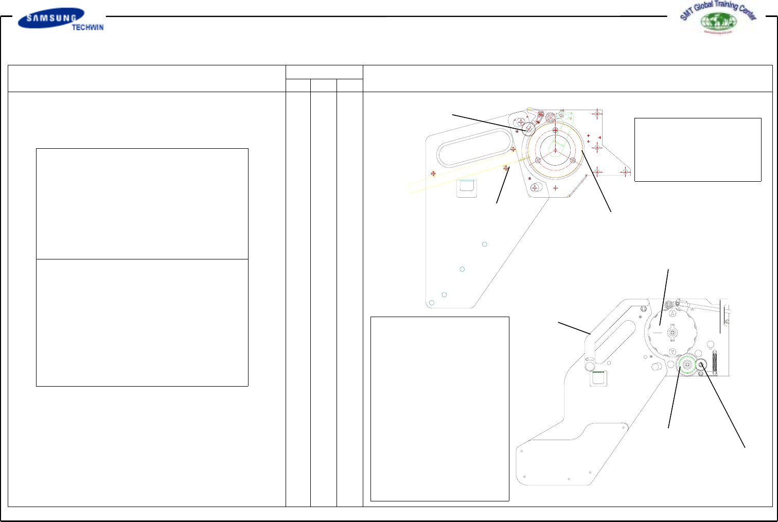
Waste Vinyl Treatment Structure &
Other Differences
1) Forming Gear
2) Drain Gear
3) Duct
1) Forming Gear
2) Drain Gear
4) Handle
3) Take up Reel ass'y
1) Only vinyl drain
structure by
combination of
No.3 part
1) Waste vinyl drain
type and take up
type realized by
combination of No.1,
2 and 3 Parts
2) No.4 handle
fixedbyconsidering
customer's
convenience and
safety.
3) Pocket installed for
the convenience of
part(roll)
replacement.
*Fixing a part(roll) to the Reel Post
-. Difficult to realize the Non Stop
function.
Part replacement impossible
during the system operation, if
feeder is mounted close together.
[See a Development Drawing]
* Fixing a part(roll) to the Pocket
-. Easy to realize the Non Stop
function with Splice Tool.
Part replacement possible during
the system operation, even
though a feeder is mounted
together.
[See a Development Drawing]
Operating Manual Reference Figure
CP-45/55 Operation Process
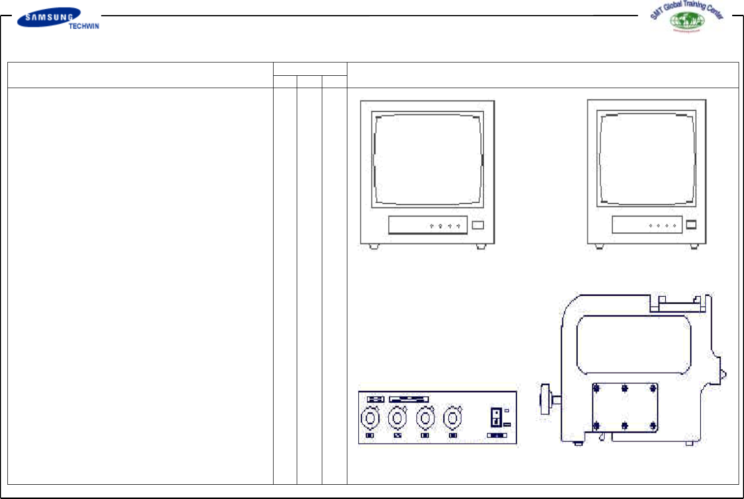
[Monitor1forSprocket
Inspection ]
[Monitor2forPocket
Inspection ]
[ Line Indicator ]
[MasterJig]
4. Adjustment of Regular
Position of Tape Feeder
4.1 Inspection Jig
4.1.1 Features of Product
This product, as the tape feeder
inspection JIG, is to
maximize the efficiency of the chip
mounter by determining the
abnormal conditions of the tape
feeder through the inspection for
errors such as defectives of
reference position, repetition
accuracy, etc. which may be
occurred by wear caused by tape
feeder operation for a long time.
4.1.2 Product Configuration and
Name
Operating Manual Reference Figure
CP-45/55 Operation Process
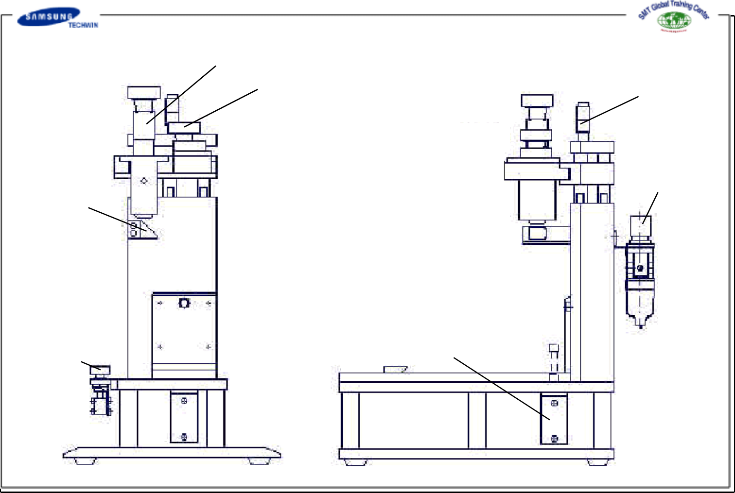
Cylinder Push
Button
Camera 1 (Sprocket Inspection)
Camera 2 (Pocket Inspection)
Reflecting Mirror
Focus Adjusting Screw
Regulator
Hydraulic Cylinder
[ Inspection JIG Body ]