SiplaceX4_en.pdf - 第100页
1 - 24 S tudent Guide SIPLACE X 3 Communication and Control Edition 09/2005 24 3.3.10 CAN: Bus Communicati on with Axis Controller In previous Siplace placement machin es, the communication and dat a flow between axis co…

1 - 23
Student Guide SIPLACE X
Edition 09/2005 3 Communication and Control
23
I/O Modul SUB Distributor: (Outputs) 3
nc= not connected (Reserve)
Connectors I / O Description / Note
X7_1 Do0
St_D0ServoSlot Bit-0 of the servo slot identification
Each servo card get a number (0-16) for the Identification. This number can be
reconstructed from all 4 servo address bus messages. In the interaction with the
outputs EA2/Do0 to EA2/Do4 every servo board can be checked in the provided
slot.
X7_2 Do1
St_D1ServoSlot / Bit-1 of the ServoSlot-Identification!
X7_3 Do2
St_D2ServoSlot / Bit-2 of the ServoSlot-Identification!
X7_4 Do3
St_D3ServoSlot / Bit-3 of the ServoSlot-Identification!
X7_5 Do4
St_D4ServoSlot / Bit-4 of the ServoSlot-Identification!
X7_6 Do5
St_pressure air main valve / ON
"low" Signal open the valve
X7_7 Do6
nc
X7_8 Do7
nc
X8_1 Do8
nc
X8_2 Do9
nc
X8_3 Do10
nc
X8_4 Do11
nc
X8_5 Do12
X8_6 Do13
X8_7 Do14
X8_8 Do15
1 - 24
Student Guide SIPLACE X
3 Communication and Control Edition 09/2005
24
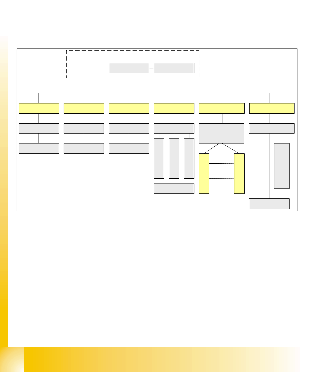
3.3.10 CAN: Bus Communication with Axis Controller
In previous Siplace placement machines, the communication and data flow between axis control-
ler and machine controller was achieved using the SMP bus. From the HF machine generation
on, the SMP bus is no longer used with the axis system.
The communication between the axis controller modules is now achieved using the CAN Bus. All
information, which has to be transfered between these modules, is now on the CAN bus (e.g axis
parameter, target position, end signal, ...) This of course means that the number of single tele-
grams increases significantly compared with the amount of data exchange which has occurred
previously.
Fig. 3.3 - 19 Overview axis controller
Computer Unit
COM Board
Machinen- CAN Bus
(1MBit/s)
X-axis
Servo board
DP - drive 20
DP drive 1
MC
Y-axis Star-axis Z-Axis DP drive (C&P20) DP-axis (C&P6/12)
Motherboard
DP Master
Axis controller A363
Step motor control
DP Swivel in
Retract unit
Component sensor
Light barrier bottom
Axis controller
A363
Axis controller
A363
Axis controller
A363
Axis controller
A363
Servo board Servo board
Servo board
Servo board
1 - 25
Student Guide SIPLACE X
Edition 09/2005 3 Communication and Control
25
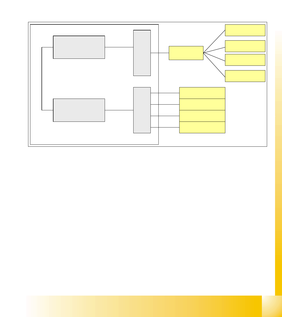
3.3.11 Communication Siplace Vision
The communication between the computers is carried out via LAN cables. The MC send the com-
mands for the image acquisition to the Visionrechner and receives the result of the measuring.
The MC send the illumination values of the corresponding GF.
The taken pictures are sent digital via the Hot link card to the Visionrechner, these evaluated the
picture.The result is sent to the MC.
Fig. 3.3 - 20 Overview Siplace Vision
Computer Unit
PCB-Camera
FC-Camera
IC-Camera
Component
Camera
Machine controller
(MC)
Sationcomputer with
Visionsoftware
LAN
Hotlink-Board
CAN Bus
Vision Board
PCB-Camera
Illumination
Comp.Camera
Illumination
FC-Camera
Illumination
IC-Camera
Illumination
Backplane
Backplane
COM-Board