SiplaceX4_en.pdf - 第409页
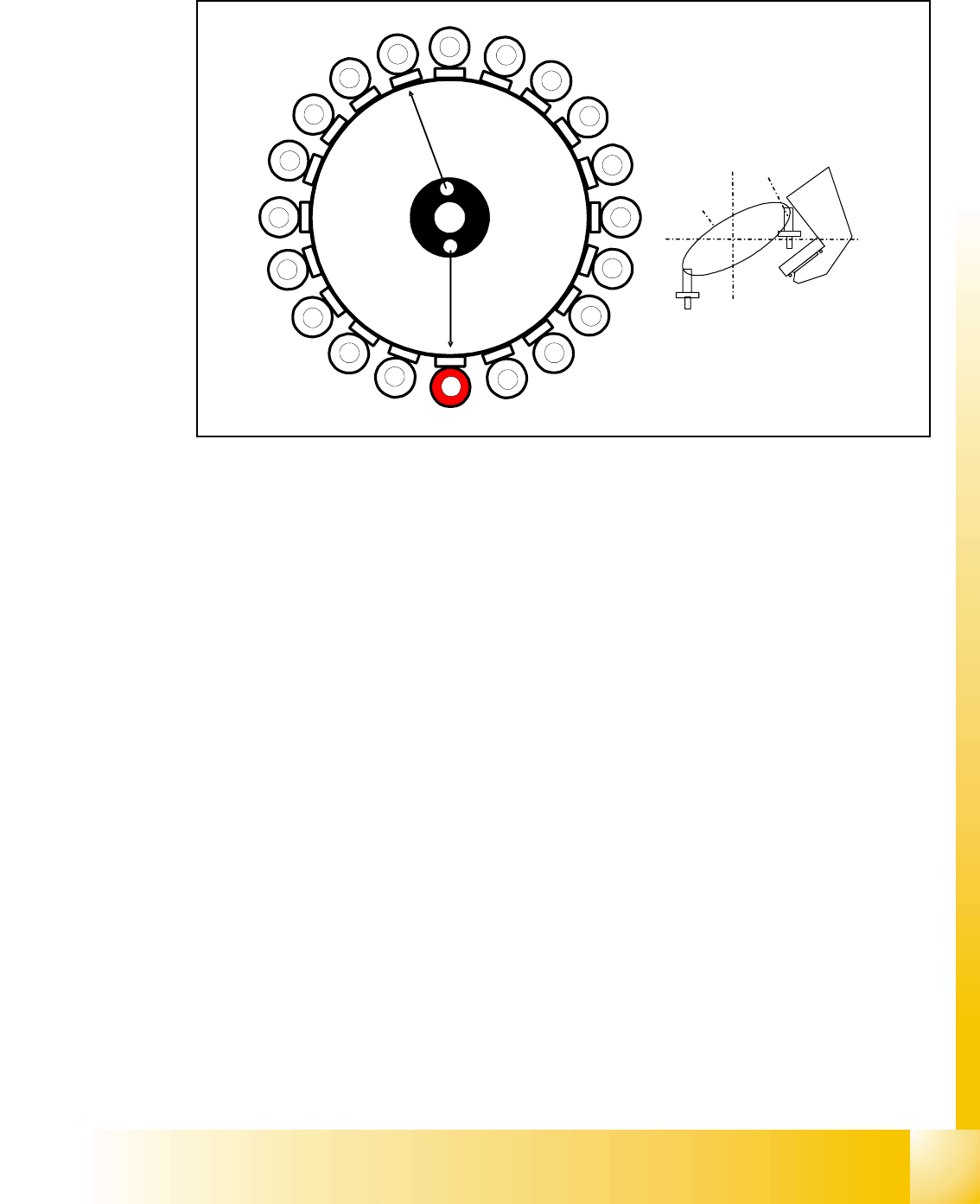
1 - 43 S tudent Guide SIPLACE X Edition 09/2005 8 Collect&Place-Head 20 43 8.3.26 St andard Placement Mode: Z-Axis Upwards Fig. 8.3 - 23 Detailed component placement sequence: Z-axis upwards LB down switches: –. . . …
1 - 42
Student Guide SIPLACE X
8 Collect&Place-Head 20 Edition 09/2005
42
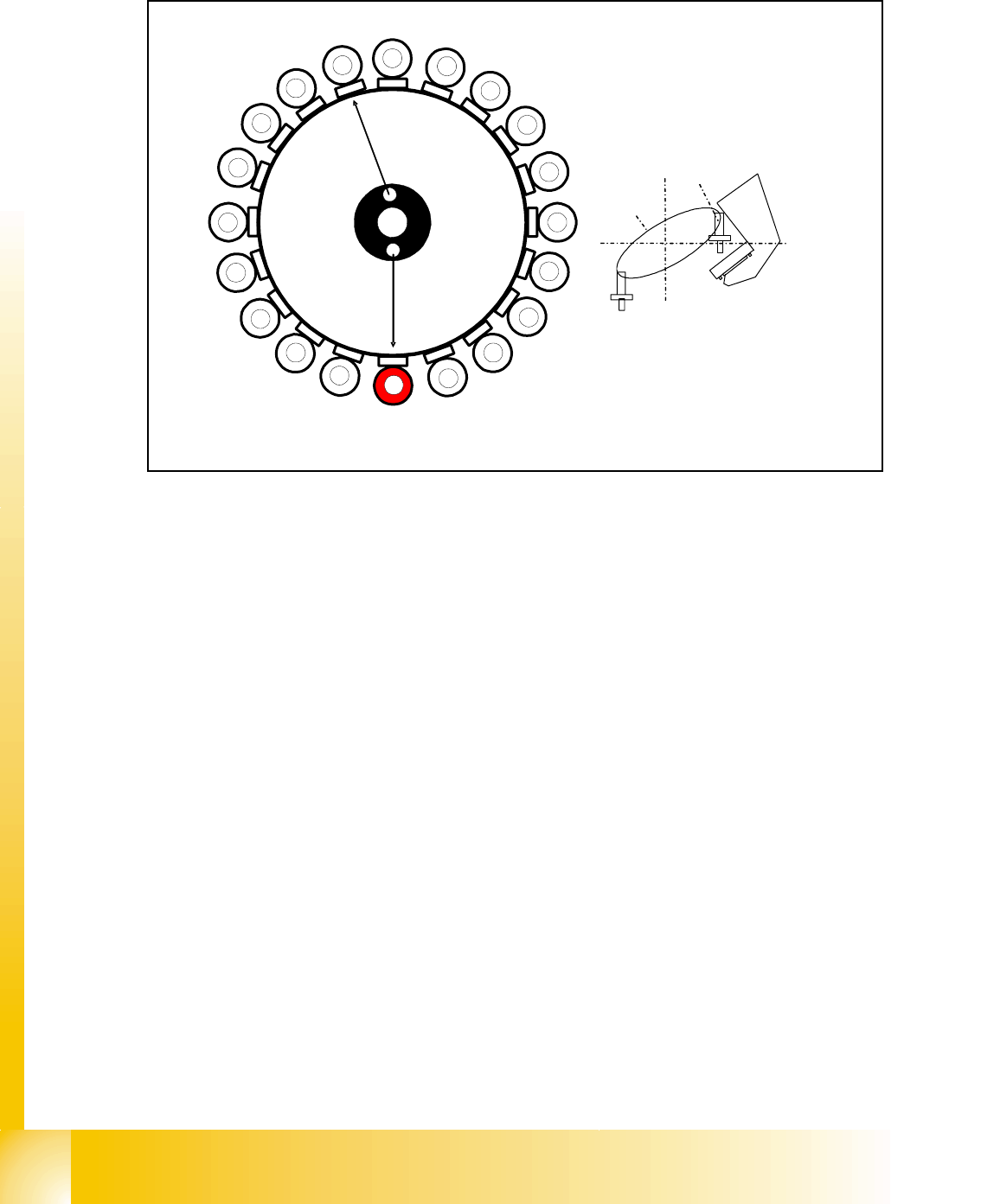
8.3.25 Standard Placement Mode: Z-Axis Downwards
Fig. 8.3 - 22 Detailed component placement sequence: Z-axis downwards
In this mode (light barrier down) the placement force at the C&P 20 head is around 2N.
End signal for X and Y axes:
Z-axis starts:
– Z-axis positioning downwards
– Component sensor checks nozzle length with component. Threshold reached?
YES
End signal for star axis:
– Performs vacuum test "before placement" Vacuum closed threshold reached? YES
to determine whether the component is held by holding force on the nozzle.
Axis controller:
– Enable signal for "light barrier down" function
LB down switches:
– End signal Z-axis positioning downwards;
– Digital pressure control valve: switches air kiss ON
– Pickup/placement position; air kiss threshold ’place component’ reached?
– ...
1
2
3
4
5
6
7
8
9
10
12
11
13
14
15
16
17
18
19
20
C
O
-
C
am
e
r
a
Segment 1
S
e
g
m
e
n
t
1
1
S
t
a
r
p
o
s
i
t
i
o
n
1 - 43
Student Guide SIPLACE X
Edition 09/2005 8 Collect&Place-Head 20
43
8.3.26 Standard Placement Mode: Z-Axis Upwards
Fig. 8.3 - 23 Detailed component placement sequence: Z-axis upwards
LB down switches:
–...
– Pickup/placement position; air kiss threshold ’place component’ reached?
– Start signal for upwards movement
Z-axis starts:
– Z-axis positioning upwards
Head firmware:
– Digital pressure control valve: switches air kiss OFF
– Reset "light barrier down" signal
Axis controller:
– Z- Axis measurement value for nozzle empty and
– Z-Axis in safe area
– Enable X-, Y- gantry axes for positioning
Vacuum check
– Vacuum check: threshold for holdig circuit reached? YES
–start Star axis.
1
2
3
4
5
6
7
8
9
10
12
11
13
14
15
16
17
18
19
20
C
O
-
C
a
m
e
r
a
Segment 1
S
e
g
m
e
n
t
1
1
S
t
a
r
p
o
s
i
t
i
o
n

1 - 44
Student Guide SIPLACE X
8 Collect&Place-Head 20 Edition 09/2005
44
8.3.27 Optical nozzle scanning
(1) After placing the first board the nozzle scanning is activated:
– All nozzles listed in the scan parameters of the machine database will be measured by the
component camera (nozzles such as 1001 - 1014).
– If there is any bright spot with a defined size and brightness the machine displays “nozzle
segment... worn out or polluted”.
(2) Tiny nozzles may touch the solder paste or the glue because of component shift and the min-
imum component height.
3. The number of components per segment (number of head cycles) after which the next nozzle
scanning is executed should be adjusted to customers process needs. This check is always
performed after completing PCB processing.
Description of Air Kiss Control During Placement 8
The air kiss is controlled by the digital pressure control valve, which can be programmed via the
component shape data in the SIPLACE PRO programming computer.