SiplaceX4_en.pdf - 第240页
1 - 12 S tudent Guide SIPLACE X 6 Collect &Place-He ad 6/12 Edition 09/2005 12 6.1.4 Pressure air supply DLM 2 C&P head Fig. 6.1 - 6 Pressure air conn ectors C&P head 6.1.4.1 V acuum generator DLM 2 Fig. 6.1 …
1 - 11
Student Guide SIPLACE X
Edition 09/2005 6 Collect &Place-Head 6/12
11
6
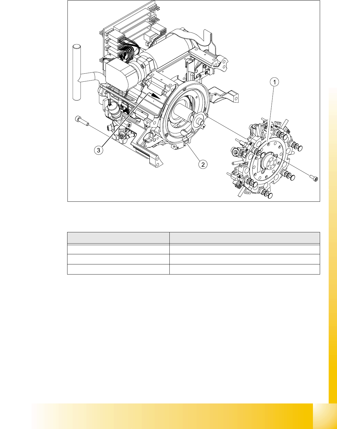
Fig. 6.1 - 5 DLM2 6 segment Collect&Place head - parts overview 3
6
Item in Fig. Designation
1 Star fitted / DLM2
2 "Z-axis down" sensor
3 RSF digital encoder 12/DLM2
1 - 12
Student Guide SIPLACE X
6 Collect &Place-Head 6/12 Edition 09/2005
12
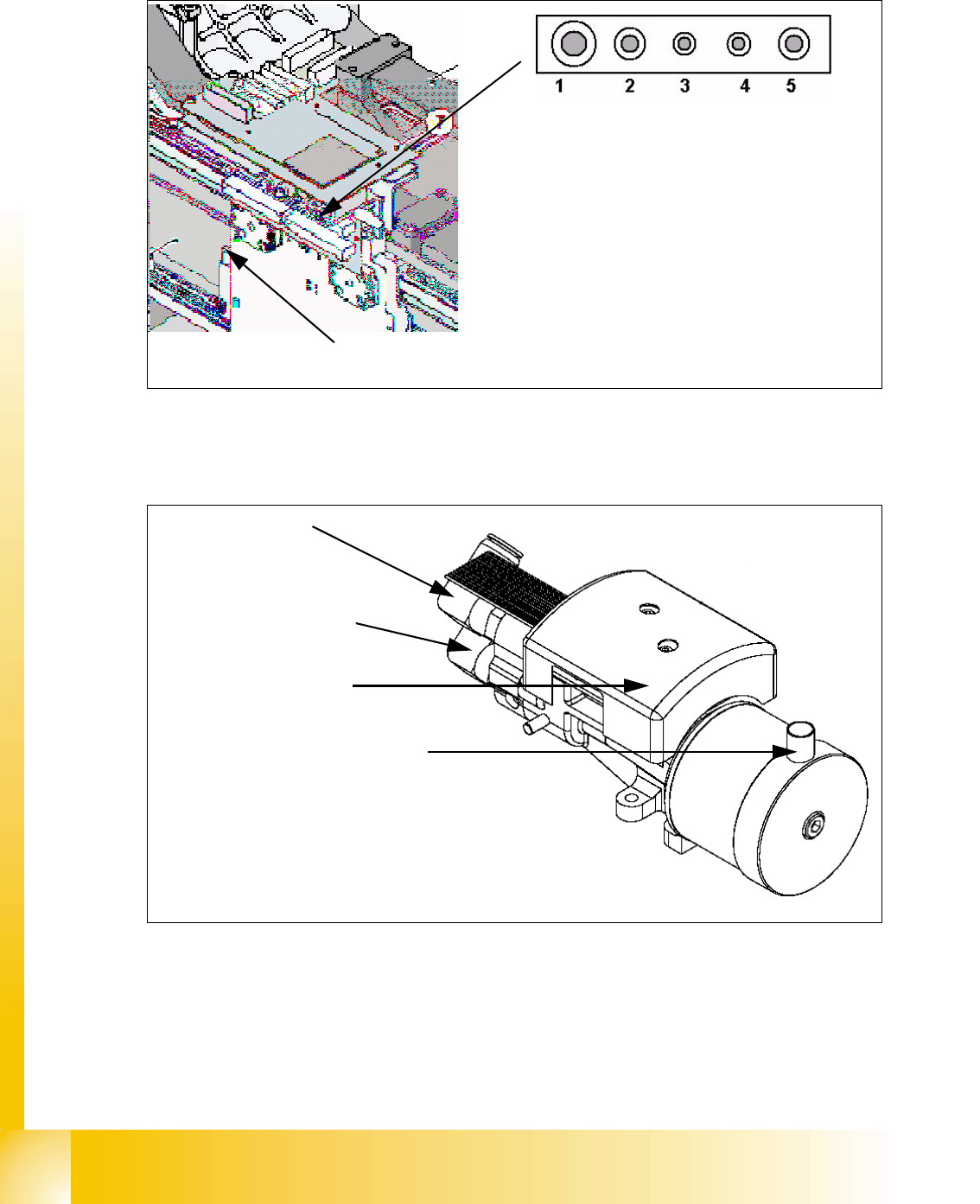
6.1.4 Pressure air supply DLM 2 C&P head
Fig. 6.1 - 6 Pressure air connectors C&P head
6.1.4.1 Vacuum generator DLM 2
Fig. 6.1 - 7 Vacuum generator DLM 2 head
(1) Pressure air connector for C&P-head Va-
cuum-holding circuit 4,7 bar Input pressure air
for the Placement head
(2) Pressure air connector for C&P-head Va-
cuum-pick up circuit with branching for the air
kiss supply 4,7 bar Input pressure air for the
Placement head
(3)-(5) Blind connector (Connector for Twin head)
Pressure air connector for cooling
X-Motor
(1) Holding circuit
(2) Pick up- and Placement circuit
w
ith branching for air kiss
V
acuum measuring board
Pressure air connector for cooling
the X-motor on the silencer (exhaust
air from the vacuum system)
1 - 13
Student Guide SIPLACE X
Edition 09/2005 6 Collect &Place-Head 6/12
13
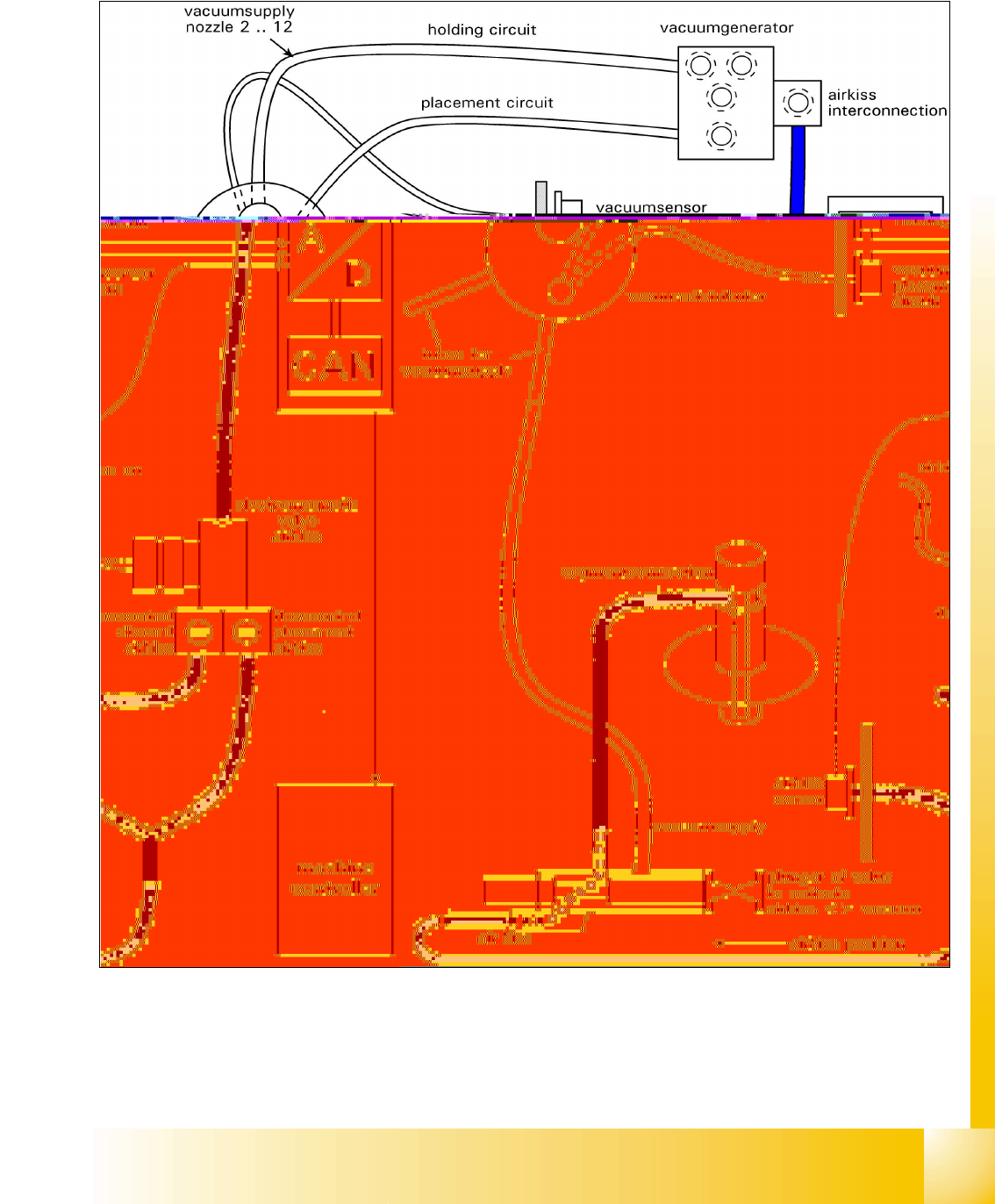
6.1.5 Overview air kiss supply
6
Fig. 6.1 - 8 General overview of the function Air kiss
6
6