SiplaceX4_en.pdf - 第219页
1 - 25 S tudent Guide SIPLACE X Edition 09/2005 5 Gantry 25 5.4.2 Check the track signals 5.4.2.1 Analog track signals T o check the track signals use the same setup which is descriped under point 5.4.1.1 . ➠ Switch the …
1 - 24
Student Guide SIPLACE X
5 Gantry Edition 09/2005
24
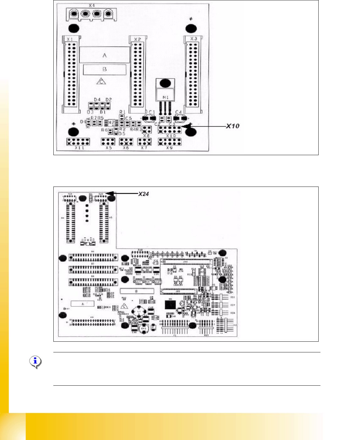
X10 on the Gantry Interface Y-axis 5
X24 on the head interface X-axis 5
Please Note:
The measurement procedure for measurment the digital zero pulse is the same as the analog zero
pulse.
Connector:
Pin 1 Ground
Pin 2 Track A
Pin 3 Track A\
A\ mean inverted A
Pin 4 Ground
Pin 5 Track B
Pin 6 Track B\
Pin 7 +5V
Pin 8 Track N
Pin 9 Track N\
Pin 10 Key
Connector:
Pin 1 Ground
Pin 2 Track A
Pin 3 Track A\
Pin 4 Ground
Pin 5 Track B
Pin 6 Track B\
Pin 7 +5V
Pin 8 Track N
Pin 9 Track N\
Pin 10 Key
1 - 25
Student Guide SIPLACE X
Edition 09/2005 5 Gantry
25
5.4.2 Check the track signals
5.4.2.1 Analog track signals
To check the track signals use the same setup which is descriped under point 5.4.1.1 .
➠ Switch the machine "ON"
➠ Switch the track signal tester to "oscilloscope calibrate"
➠ Oscilloscope adjustments "DC, Refr., Non Store, Auto (20 ms)"
➠ Voltages V/Division decrease up to 0,5 V/Div.
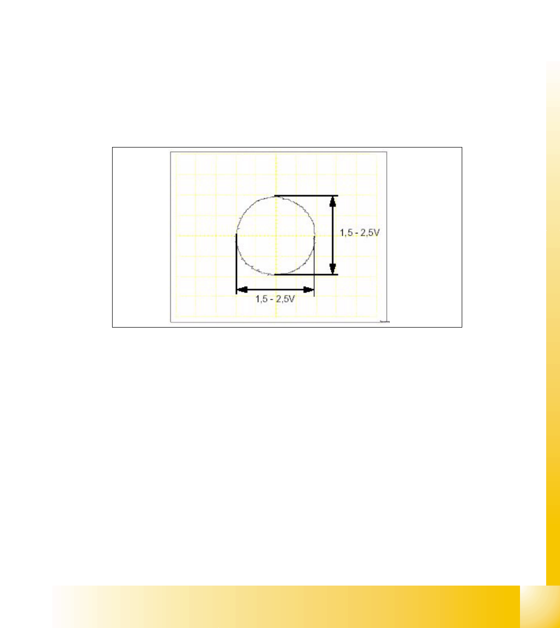
➠ Oscilloskope adjust to the position "X / Y" ==> a point appears !
➠ Move the point into the middle of the display
➠ Switch the track signal tester to"Sinus amplifier output"
➠ Move the axis by hand over the whole incremental scale (to check the scale quality).
➠ It should be appears the following picture.
Fig. 5.4 - 6 Analog track signals A and B in X/Y mode
➠ Switch the oscilloscope to the normal mode.
➠ It should be appears the following picture.
1 - 26
Student Guide SIPLACE X
5 Gantry Edition 09/2005
26
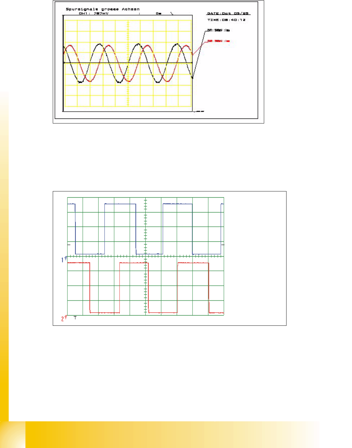
Fig. 5.4 - 7 Analog track signals 90° phase shift
5.4.2.2 Digital Track signals
To check the track signals use the same test setup which is descriped under point 5.4.1.2 .
The measurement procedure is the same as descriped under point 5.4.2.1 .
Fig. 5.4 - 8 Digitale track signals 90° phase shift
Spur A / track A
Spur B / track B