SiplaceX4_en.pdf - 第251页
1 - 23 S tudent Guide SIPLACE X Edition 09/2005 6 Coll ect &Place-Head 6/12 23 6.2.7 Determining the V ac uum and Threshold V alues Fig. 6.2 - 9 Measuring and calculating t he vacuum values for a reference run 1. The…
1 - 22
Student Guide SIPLACE X
6 Collect &Place-Head 6/12 Edition 09/2005
22
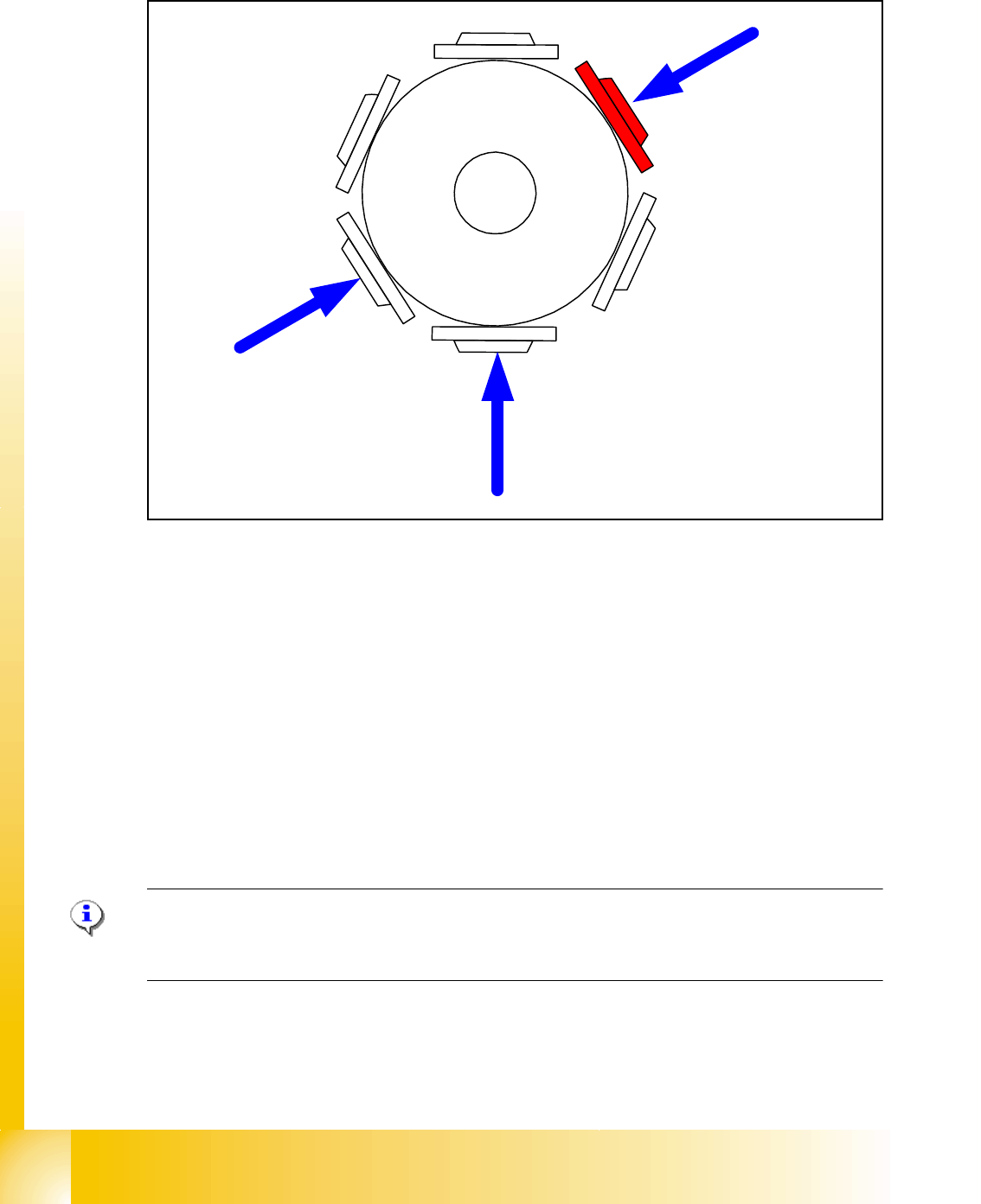
6.2.6 Pollution and Components are Rejected / Nozzles Turned to 0°
Fig. 6.2 - 8 Sequence vacuumcheck
– The Gantry axes move the Collect & Place head to the reject position.
– The star axes move anticlockwise and all three functions are carried out within a head cycle
and at same time (see Fig. 6.2 - 8).
1. The DP-station is swiveled in and turns each segment to 0° position.
2. The air kiss valve is opened, the valve drive of the reject position is activated and switches
between open and closed. Anything on the nozzle is rejected.The air kiss valve is closed.
3. The vacuum reference values at the pick-up
/ placement station are measured.
– These are the reference values for each segment for the vacuum checks during placement.
– These three steps are executed parallel.
Note:
The position 2 in Fig. 6.2 - 8 will used only on the X4 and X3/X2 Machine. The reject position on
the Siplace HF and SIPLACE X is below at position 3.
4
1
5
2
3
6
1
3
2
1 - 23
Student Guide SIPLACE X
Edition 09/2005 6 Collect &Place-Head 6/12
23
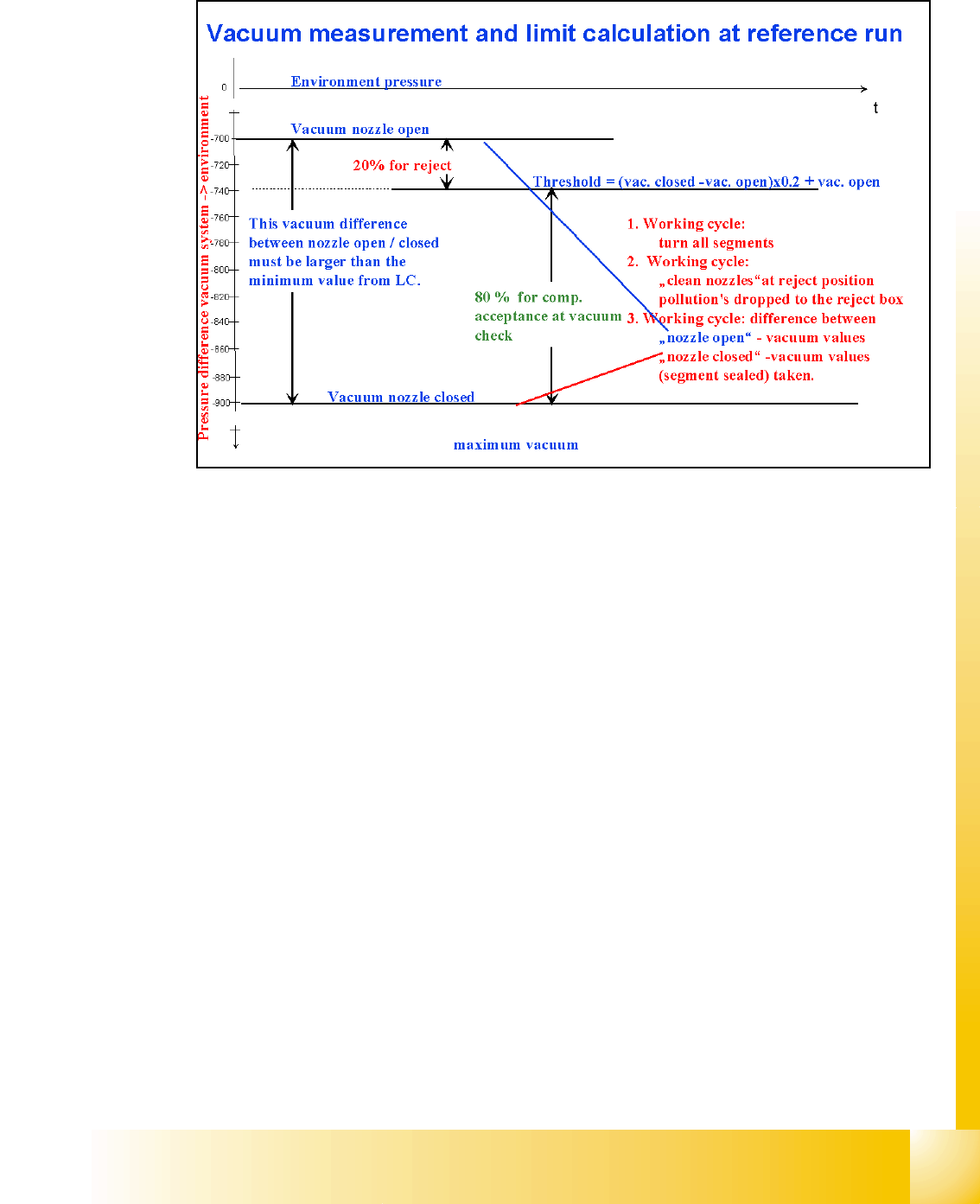
6.2.7 Determining the Vacuum and Threshold Values
Fig. 6.2 - 9 Measuring and calculating the vacuum values for a reference run
1. The vacuum is measured twice at the reference point: once with closed and once with open
valve, while air flows through the nozzle.
2. The value with closed valve depends on the ambient pressure and may vary significantly, ac-
cording to the local weather conditions and altitude. In principle, the rule applies that the
greater the altitude at the machine installation site (higher ambient pressure), the lower the
vacuum by closed valve.
3. The value by open valve depends on the nozzle size and condition. The smaller the nozzle,
the greater the open valve value will be. A contaminated or blocked nozzle will also give a
higher valve.
4. The difference between the open and closed nozzles has been preset by the line computer as
an ideal case minimum value. This value is different for all nozzle types e.g. 120 mbar for 714,
704, 914 and 904 nozzles. If these values are not achieved, the error message "Vakuumdiffer-
enz offen-geschlossen zu gering" (vacuum difference open-closed is too low) will appear.
5. The threshold for component acceptance is also set now. In this case, we have a value of 700
mbar by open nozzle and 900 mbar by closed nozzle. The calculation is as follows:
Threshold = (900(closed) - 700(open))= x 0.2 + 700(open)
= 200 x 0.2 + 700
= 740
1 - 24
Student Guide SIPLACE X
6 Collect &Place-Head 6/12 Edition 09/2005
24
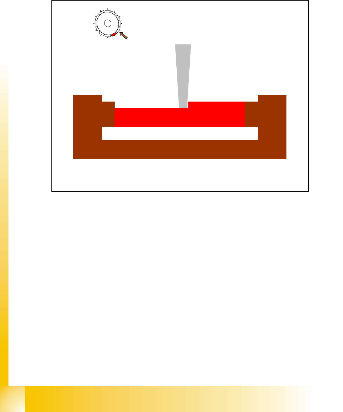
6.2.8 Measuring Nozzle Lengths for Component Recognition by the Component
Sensor
Fig. 6.2 - 10 Nozzle length reference values for component recognition in the component sensor option
The component sensor option can only be used with machine stations SW 503 or higher and only
with 12 nozzle C&P placement heads.
If the component sensor option is installed at the 12-nozzle component head, the following mea-
surement will be performed during the vacuum reference run:
The length of the nozzle in the IR beam during star revolution.
The SIPLACE PRO/ line computer defines which nozzle types can be measured (nozzle lengths
greater than 12 mm). Nozzle setup on the placement star triggers measurement.
Before component pickup, the length of the empty nozzle is checked against the value measured
during the reference run.
During the placement process, component recognition refers to the empty nozzle measurement
value before placement is performed.
2
3
4
5
6
7
8
9
1
0
1
1
12
1
IR-Sender
IR-Empfänger
Pipette
Nozzle
IR-Receiver
IR-Transmitter