SiplaceX4_en.pdf - 第158页
1 - 12 S tudent Guide SIPLACE X 4 Services to the machine Edition 09/2005 12 4.2.4.2 T ransformer 1 The main re ason for th e transformer T1 is to power the X/Y and star axis, protec ted by F4. Con - tactors K2, K3 and K…
1 - 11
Student Guide SIPLACE X
Edition 09/2005 4 Services to the machine
11
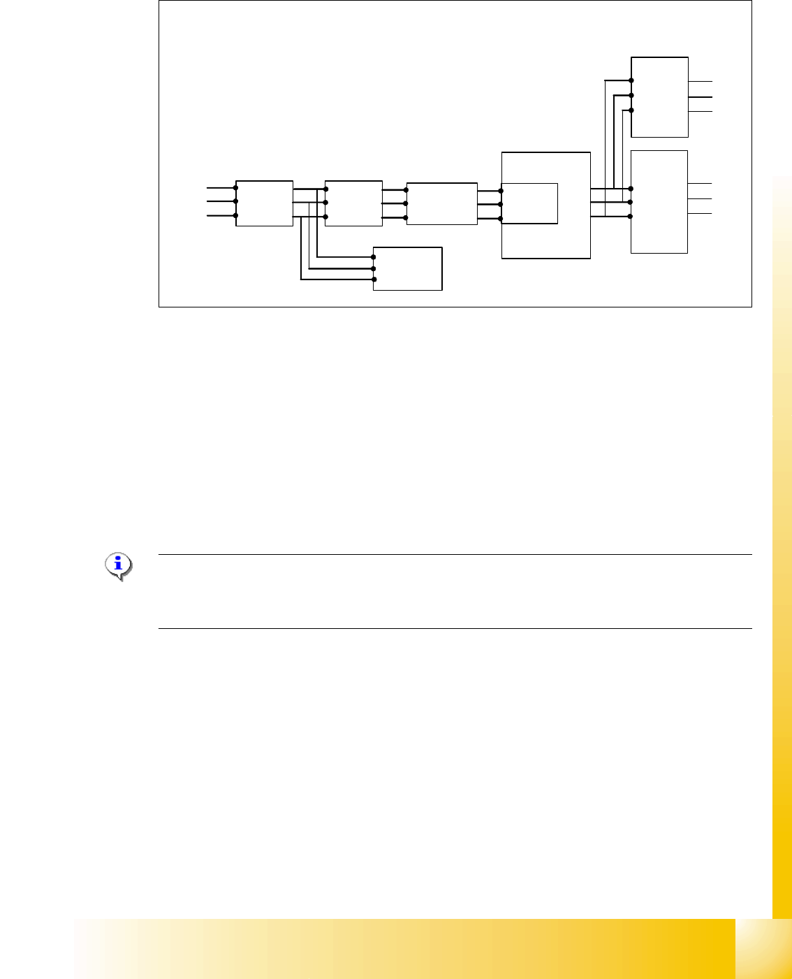
4.2.4.1 Input Voltage
Fig. 4.2 - 5 input voltage
Legend
Q1: main switch
Q2: motor circuit breaker
K1: main contactor and inrush current limiter for T1
T1: transformer 1
T2: transformer 2
L20: unloading thrush
Note:
After the transformer T1 and T2, the main power potential end and only secundary voltages supply
the machine
Q1
Q2
K1
3 phase
U
V
W
T1
U
V
W
T2
3x 230 V
Ínrush current
limiter for T1
L1
L2
L3
power
filter
L20
1 - 12
Student Guide SIPLACE X
4 Services to the machine Edition 09/2005
12
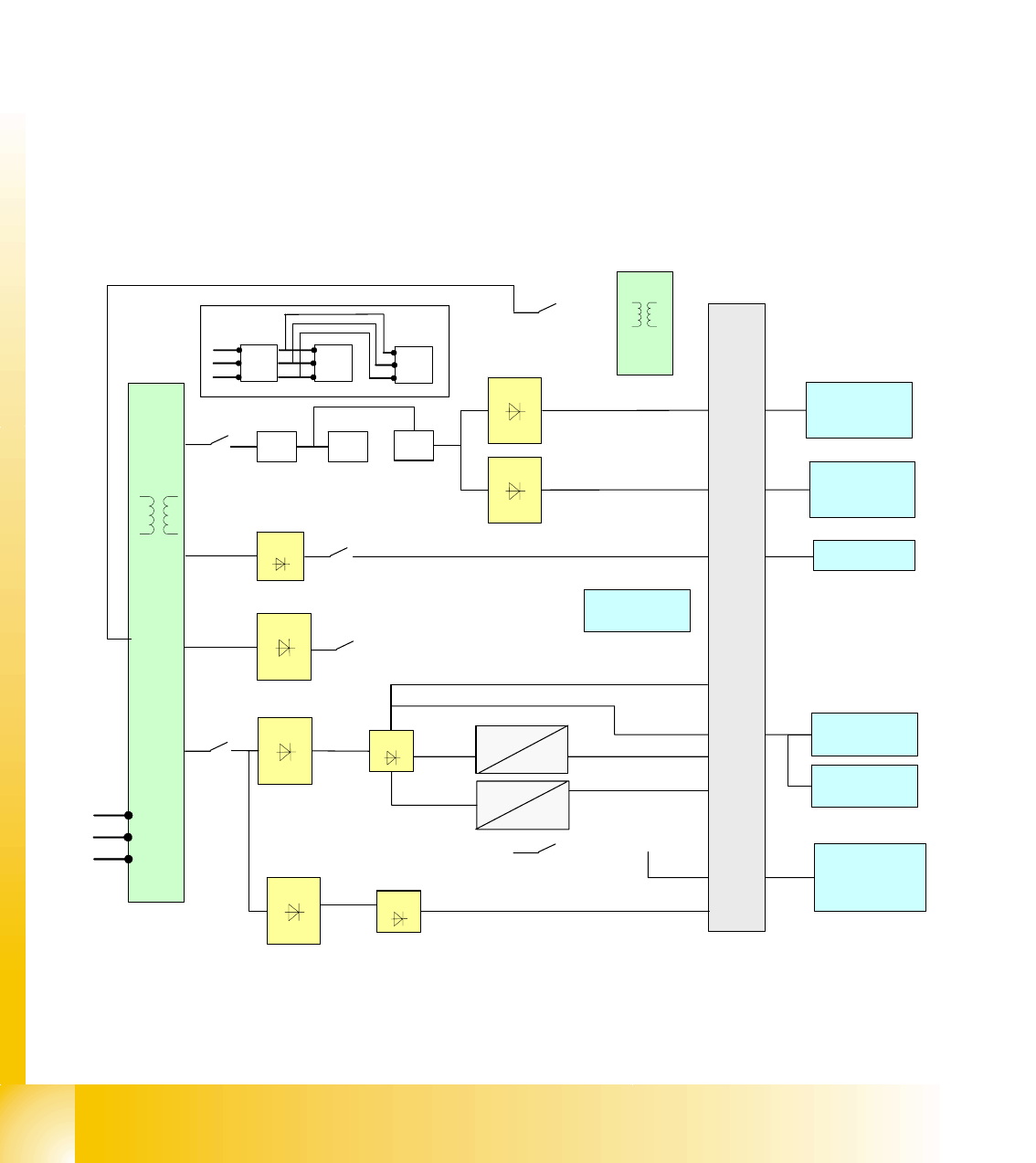
4.2.4.2 Transformer 1
The main reason for the transformer T1 is to power the X/Y and star axis, protected by F4. Con-
tactors K2, K3 and K4 illustrate fixed elements of the electrical safety concept. In a fault event, e.g.
open cover, the servos are disconnected from the energy.
The power supply unit provides the following supply voltages:
4
Primary Transformer T1 4
– 250 VDC for the servo amplifiers of the x and y axes.
– 150 VDC servo amplifiers of the star axis.
– 34 VDC for the inrush current limiter servo
– 52 VDC for the DC/DC converters in the main power unit
– 52 VDC for camera illumination and computer unit DC/DC converter
Fig. 4.2 - 6 overview transformer T1
T1
main distributor power supply
X/Y servo
U7
U70
250 VDC
52 VDC
52 VDC
24 VDC
52 VDC
24/5 VDC
F11
F12
U6
U60
power fail Twin head
U8
F10
34 VDC
K2 K3
K4
F4
K2 K3
K4
U1
U2
F5
U3
150 VDC
X/Y servo
250 VDC
star servo
SZ1 (Inrush
current delay)
3 phase
3 phase
3 phase
3 x 230 V
T2
F7
DC/DC
computer unit
52 VDC
L1
L2
L3
DC/DC axis
unit
camera
illumination
P&P camera