SiplaceX4_en.pdf - 第32页
1 - 8 S tudent Guide SIPLACE X 2 Overview Edition 09/2005 8 Configuration Siplace X2 2 Fig. 2.1 - 5 Possible configuration for Siplace X2 Note: in placement area 2, always configure a placemen t head which can handle tal…
1 - 7
Student Guide SIPLACE X
Edition 09/2005 2 Overview
7
Configuration: - C&P20 heads may only be used with X-feeders.
- A combination of C&P20 and DLM heads in one placement area is
not possible. 2
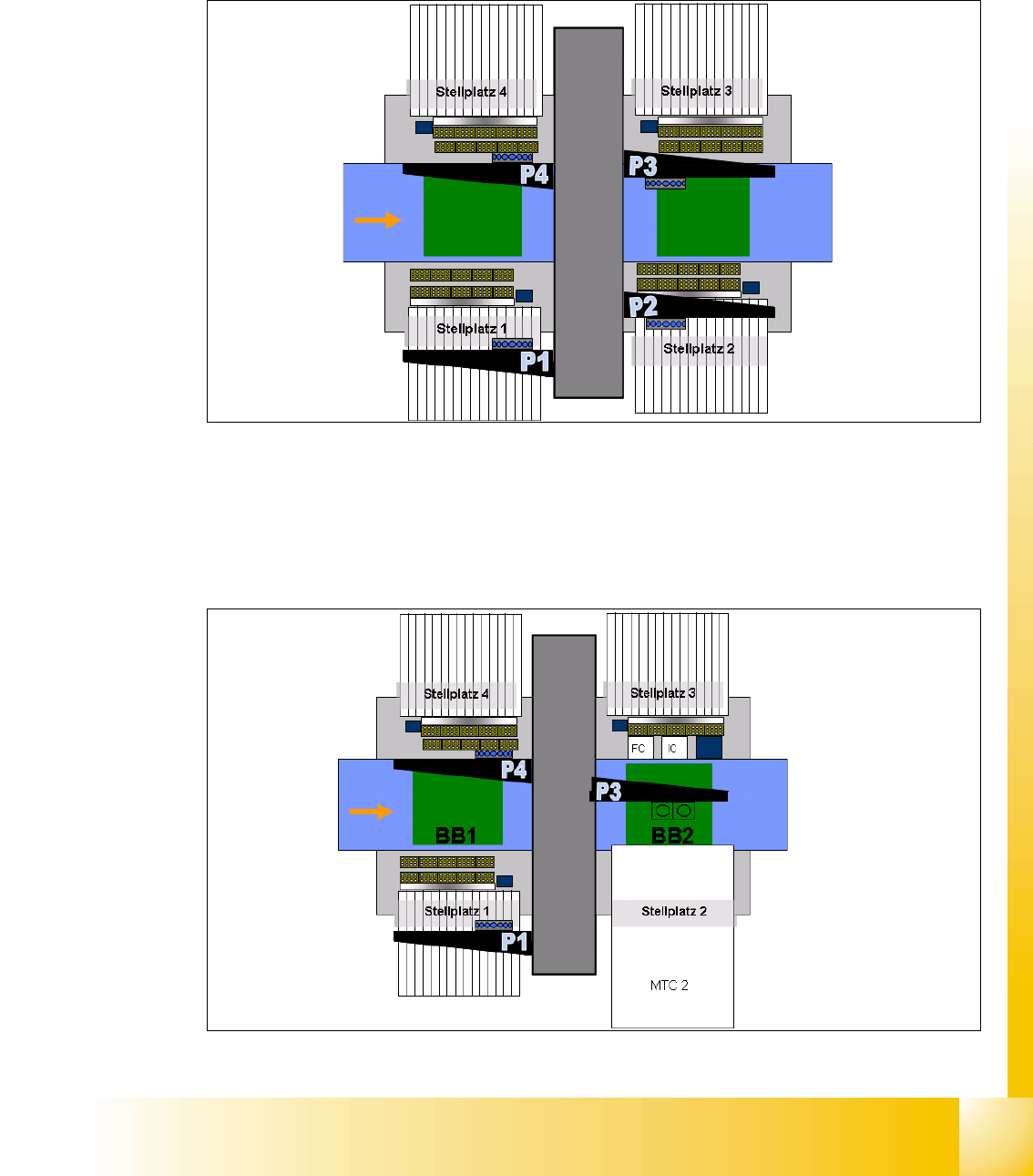
Configuration Siplace X4 2
Fig. 2.1 - 3 Possible configuration for Siplace X4
Restriction: when configuring the head, take the maximum component heights for the respective
placement heads into account.
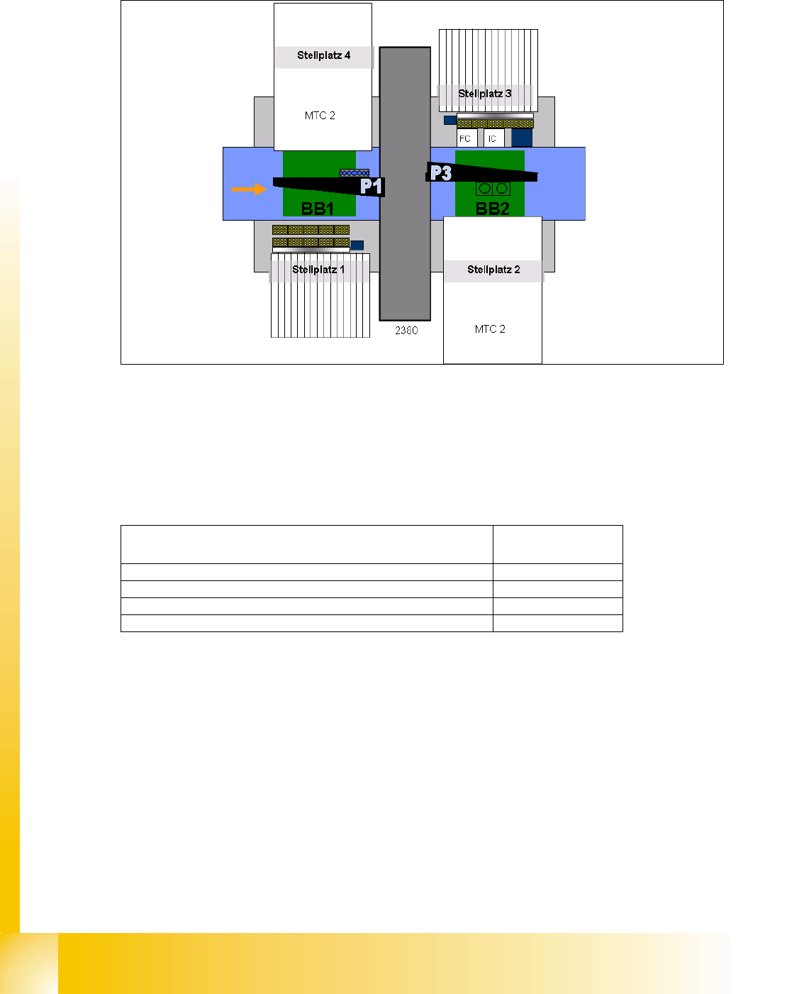
Configuration Siplace X3 2
Fig. 2.1 - 4 Possible configuration for Siplace X3
PCB transport
5 areas
C&P12, C&P6
or C&P20
C&P12, C&P6
or C&P20
Direction of-
PCB transport
C&P12, C&P6
or C&P20
C&P12, C&P6 or
C&P20
Dimensions (LxW):
2.38 x 2.75 m
15 locations per
S-table / 40 tracks for
8mm X-feeder
15 locations per S-table
40 tracks for 8mm X-feeder
PCB transport
5 areas
Twin head, C&P12
or C&P6
Component table or
MTC 2
C&P12, C&P6
or C&P20
Direction of
PCB transport
Component table
C&P12, C&P6
or C&P20
Dimensions
(LxW): 2.38 x
1 - 8
Student Guide SIPLACE X
2 Overview Edition 09/2005
8
Configuration Siplace X2 2
Fig. 2.1 - 5 Possible configuration for Siplace X2
Note: in placement area 2, always configure a placement head which can handle taller compo-
nents than the placement head in placement area 1.
Overview of placement head component heights: 2
PCB transport
5 areas
Twin head, C&P12
or C&P6
Component table
or MTC 2
Direction of
PCB transport
15 locations per
S-table / 40 tracks for
8mm X-feeder
Component table
or MTC 2
C&P12, C&P6
or C&P20
Placement heads Max. component
height
C&P6 DLM2 8.5mm
C&P12 DLM2 6.0mm
C&P20 head 4.0mm
Twin head 25.0mm
1 - 9
Student Guide SIPLACE X
Edition 09/2005 2 Overview
9
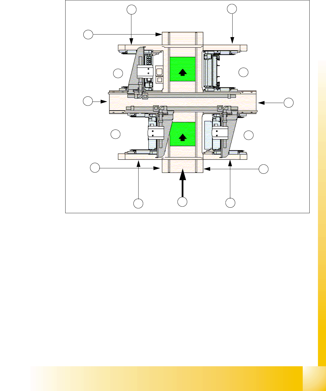
2.2 Overview of Units
Fig. 2.2 - 1 Top view Siplace X3
Key
(1) Sector 1 (2) Sector 2 (main distributor)
(3) Sector 3 (4) Sector 4 (subdistributer)
(5) Transport direction (6) Pneumatic unit & control unit conveyor
(7) Component changeover table location (8) Computer unit
(9) Location for component changeover table
or MTC 2 for BB 2
(10) Location for component changeover table
or MTC 2 for BB 1 (MTC only X2)
(11) Axis unit in PA 1(BB1) (12) Axis unit in PA 2
(13) Power supply unit
1
2
8
3
5
6
4
7
7
9
10
11
BB 1
BB 2
13
12