SiplaceX4_en.pdf - 第31页
1 - 7 S tudent Guide SIPLACE X Edition 09/2005 2 Overview 7 Configuration: - C&P20 heads may only be used with X-feeders. - A combina tion of C&P20 and DLM heads in one placement area is not possible. 2 Configura…
1 - 6
Student Guide SIPLACE X
2 Overview Edition 09/2005
6
These data provide basic information for the HF specification. The specification data valid for your
particular machine can be found in your ’Scope of delivery’ document.
Overview Head Modularity and Benchmark Performance for Selected Configuration Options2
No. tracks 8mm per component table (S-table)
45
No. tracks 8mm X-feeder per X-table
40
PCB widths for single conveyor 50 - 508 mm
Max. PCB lengths for single conveyor (long board option) 50 - 450 mm (610)
Max. PCB widths for dual conveyor
single mode operation
2 x 50-216mm (250 mm)
50-380mm (450mm)
Max. PCB lengths for dual conveyor (long board option) 50 - 450 mm (610)
PCB thickness 0.3 - 4.5mm
Conveyor speed 50 -450 mm/s
Max. PCB weight 3 kg
PCB edge clearance 3 mm
PCB changeover time < 2.5 s
Machine dimensions (L x W) ca. 2380 x 2525mm
Height of PCB transport 830 - 950mm +/- 15mm
Compressed air pressure 5 - 8 bar
Compressed air consumption (C&P12 - twin head or C&P6 - twin
head)
~ 350 NL/min.
Compressed air consumption (C&P20) ~ 200 NL/min.
Placement head combination Placement capacity
PA1 C&P20 - C&P20
40.000 cph
PA1 C&P12 - C&P12
26.800 cph
PA1 C&P6 - C&P6
18.600 cph
PA2 C&P12 - C&P6
20.300 cph
PA2 C&P12
14.000 cph
PA2 C&P6
9.300 cph
PA2 Twin Head
3.700 cph
– cph = components per hour
– PA = Placement area
1 - 7
Student Guide SIPLACE X
Edition 09/2005 2 Overview
7
Configuration: - C&P20 heads may only be used with X-feeders.
- A combination of C&P20 and DLM heads in one placement area is
not possible. 2
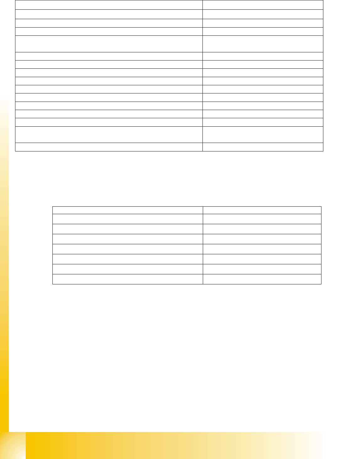
Configuration Siplace X4 2
Fig. 2.1 - 3 Possible configuration for Siplace X4
Restriction: when configuring the head, take the maximum component heights for the respective
placement heads into account.
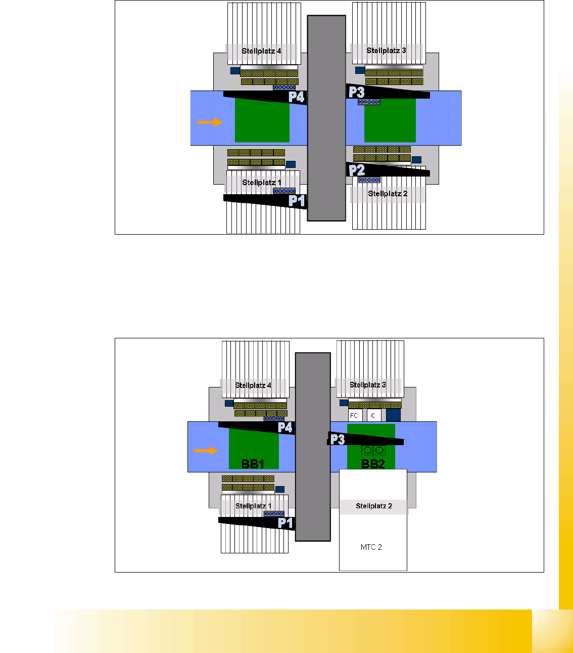
Configuration Siplace X3 2
Fig. 2.1 - 4 Possible configuration for Siplace X3
PCB transport
5 areas
C&P12, C&P6
or C&P20
C&P12, C&P6
or C&P20
Direction of-
PCB transport
C&P12, C&P6
or C&P20
C&P12, C&P6 or
C&P20
Dimensions (LxW):
2.38 x 2.75 m
15 locations per
S-table / 40 tracks for
8mm X-feeder
15 locations per S-table
40 tracks for 8mm X-feeder
PCB transport
5 areas
Twin head, C&P12
or C&P6
Component table or
MTC 2
C&P12, C&P6
or C&P20
Direction of
PCB transport
Component table
C&P12, C&P6
or C&P20
Dimensions
(LxW): 2.38 x
1 - 8
Student Guide SIPLACE X
2 Overview Edition 09/2005
8
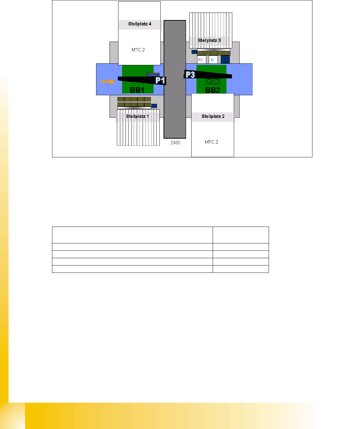
Configuration Siplace X2 2
Fig. 2.1 - 5 Possible configuration for Siplace X2
Note: in placement area 2, always configure a placement head which can handle taller compo-
nents than the placement head in placement area 1.
Overview of placement head component heights: 2
PCB transport
5 areas
Twin head, C&P12
or C&P6
Component table
or MTC 2
Direction of
PCB transport
15 locations per
S-table / 40 tracks for
8mm X-feeder
Component table
or MTC 2
C&P12, C&P6
or C&P20
Placement heads Max. component
height
C&P6 DLM2 8.5mm
C&P12 DLM2 6.0mm
C&P20 head 4.0mm
Twin head 25.0mm