SiplaceX4_en.pdf - 第322页
1 - 6 S tudent Guide SIPLACE X 7 T win-Head Edition 09/2005 6 7.1.2.1 V acuum generator T win- Head The vacuum generator controls the vacuum, air ki ss and th e zero balancing positio n (middle Po- sition-->no vacuum …
1 - 5
Student Guide SIPLACE X
Edition 09/2005 7 Twin-Head
5
7.1.2 Parts on the Twin- Head
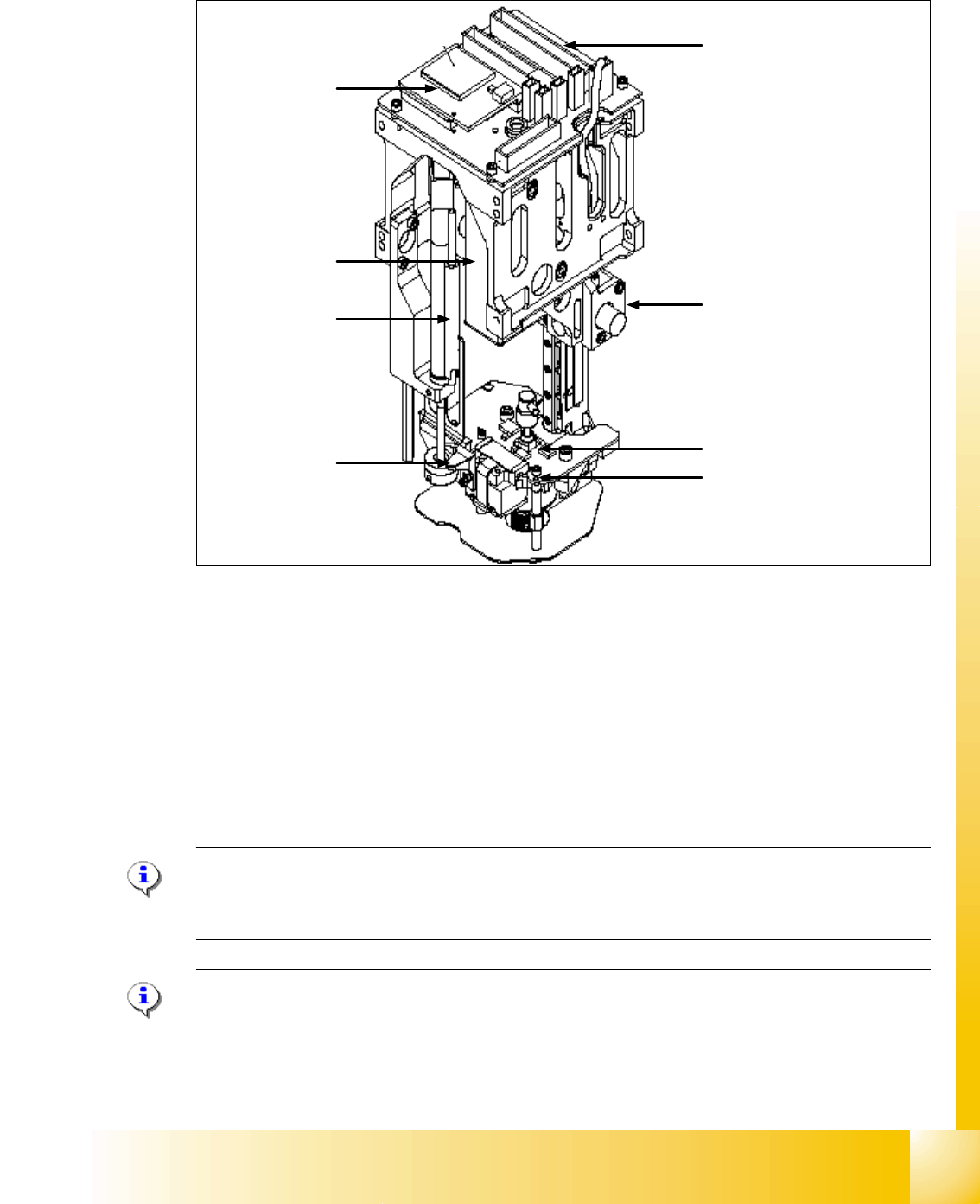
Fig. 7.1 - 3 Parts TWIN- head
1. CAN Bus Processor board ( not mounted, is now on the Head interface C500)
2. Main board TWIN- head
3. D-axis complete with incremental encoder and force sensor
4. Incremental encoder Z-axis
5. Retract unit to return the Z-axis in a safety area in case of power fail
6. Vacuum generator
7. Actuator retract unit (right) / Screw on the force measurement board (left)
Please Note:
Please use this two Positions (7) to move manually the Z-Axis downwards if the Servo board
switch off (Switch off the Axis card)!
Please Note:
The parts 1, 2, 4, 5 and 6 are spare parts and the whole module. ( Service manual).
4
3
2
5
1
6
7
7
1 - 6
Student Guide SIPLACE X
7 Twin-Head Edition 09/2005
6
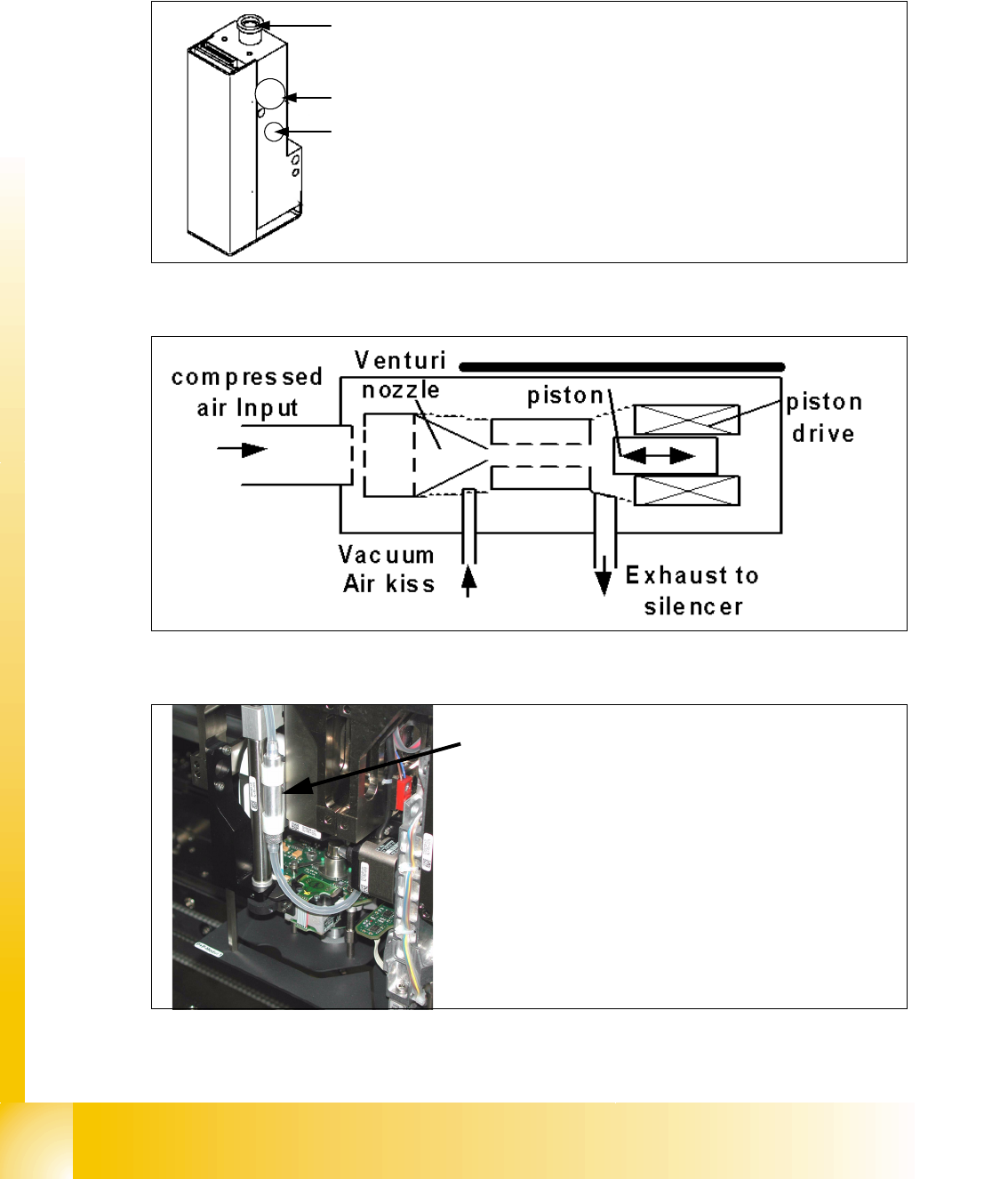
7.1.2.1 Vacuum generator Twin- Head
The vacuum generator controls the vacuum, air kiss and the zero balancing position (middle Po-
sition-->no vacuum and no air kiss) for the segments with a aid of a linear motor automatically.
Fig. 7.1 - 4 Vacuum generator
Fig. 7.1 - 5 Principle of the vacuum generator
Fig. 7.1 - 6 Filter for the vacuum generator
1
3
2
1. Compressed air input
2. Exhaust air to the silencer and cooling the X-linear motor
3. Output vacuum that go to the D-axis motor through the
shaft of the motor and then to the nozzle.
Filter for the vacuum system on the TWIN- head.
The Filter is mounted on the retract unit and used as an
attenuator to control the vacuum. Together with the defi-
ned length of the silicon pipe reduce the attenuator the
oscillation of the vacuum generator and guaranteed an
accurate vacuum- and air kiss supply.
The filter need a regular maintenance interval (see pre-
ventive maintenance manual).
1 - 7
Student Guide SIPLACE X
Edition 09/2005 7 Twin-Head
7
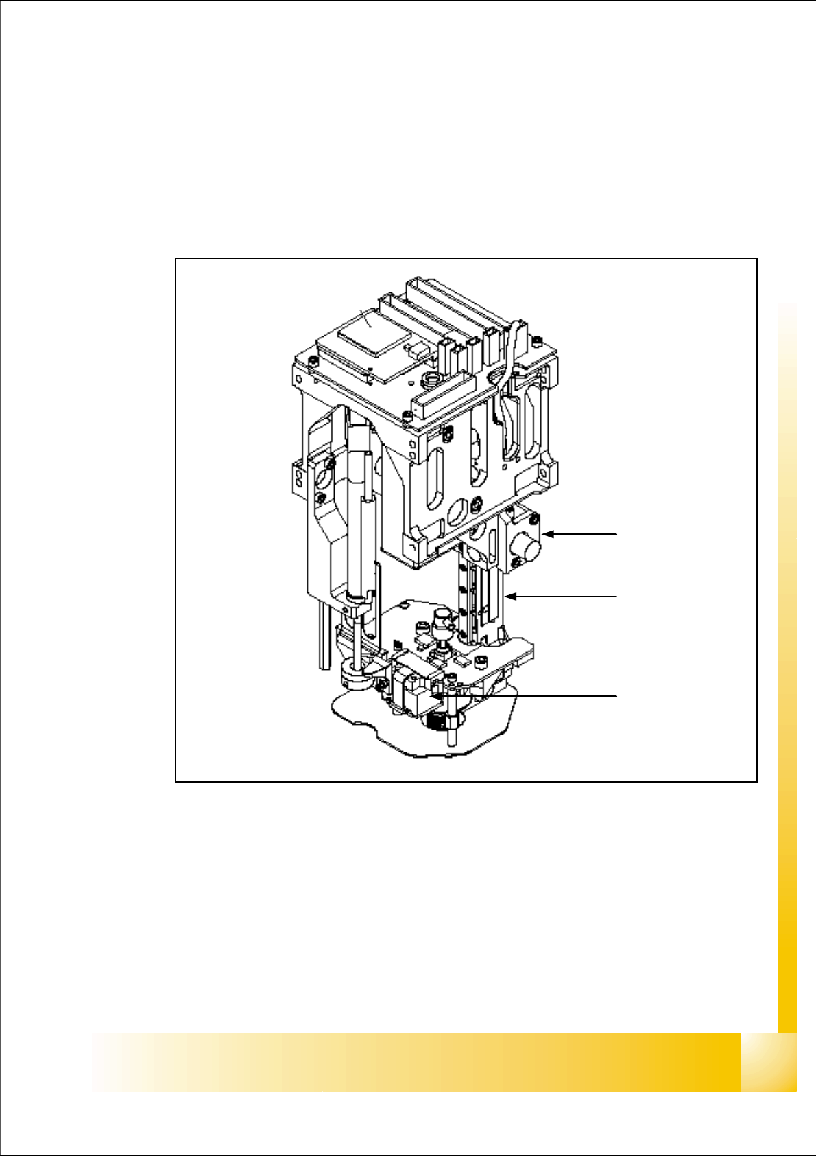
7.2 Reference Run Twin-head
The TWIN-head consist of two segments which have 2 axes Z and D and the X and Y axes at the
Gantry.
Before you start the reference run the retract cylinder move out to the lower home position. On
both modules the vacuum is on, until the vacuum generator is initialized.
Fig. 7.2 - 1 TWIN-head Z,D- axes
1. Z-axis incremental encoder
2. Z-axis linear incremental scale
3. D-axis incremental encoder with incremental glass scale
1
3
2