SiplaceX4_en.pdf - 第418页
1 - 52 S tudent Guide SIPLACE X 8 Collect&Place-Head 20 Edition 09/2005 52 8.5.2 Det ail view of no zzle changer C&P 20 head Fig. 8.5 - 2 Detail view of nozzle changer 20 segment C&P head Legend lef t picture…
1 - 51
Student Guide SIPLACE X
Edition 09/2005 8 Collect&Place-Head 20
51
8.5 Nozzle changer
The Siplace X is supplied with 6 segment -, 12 segment- or 20 segment Collect&Place heads. As
an option, nozzle changer can be installed for each collect&place head type. This enables the noz-
zle configuration to be changed quickly, thus allowing the collect&place head to be quickly
adapted to the needs of the placement process. The nozzle changer configuration for C&P20
looks as follows.
8.5.1 Nozzle changer for C&P 20 head
The nozzle changer consists of six magazines, each with twelve nozzle garages (see Fig. 8.5 -
2),how the individual garages freely are configurable. Every magazine is clampt on the basic body
with 4 push buttons. The magazine can be removed by the activity one for tipping over lever (per
magazine of one).The magazines are seated on a common support and each magazine is cen-
tered using two parallel pins and another pin is used to move the magazine shutter. A visual report
(green LED) shows, with the help of the built-in microswitches, whether all magazines are locked
correctly at the nozzle changer carrier.
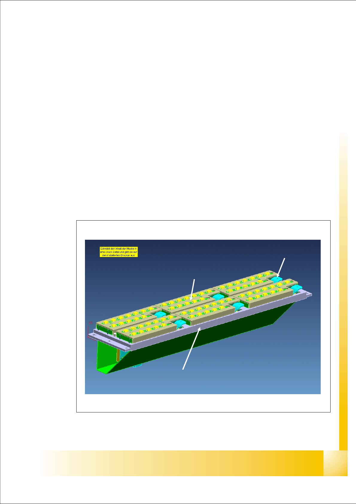
Fig. 8.5 - 1 main view - nozzle changer and nozzle magazin 20 segment C&P head
tipping over lever to remove the
magazine
nozzle changer basic body
magazine
1 - 52
Student Guide SIPLACE X
8 Collect&Place-Head 20 Edition 09/2005
52
8.5.2 Detail view of nozzle changer C&P 20 head
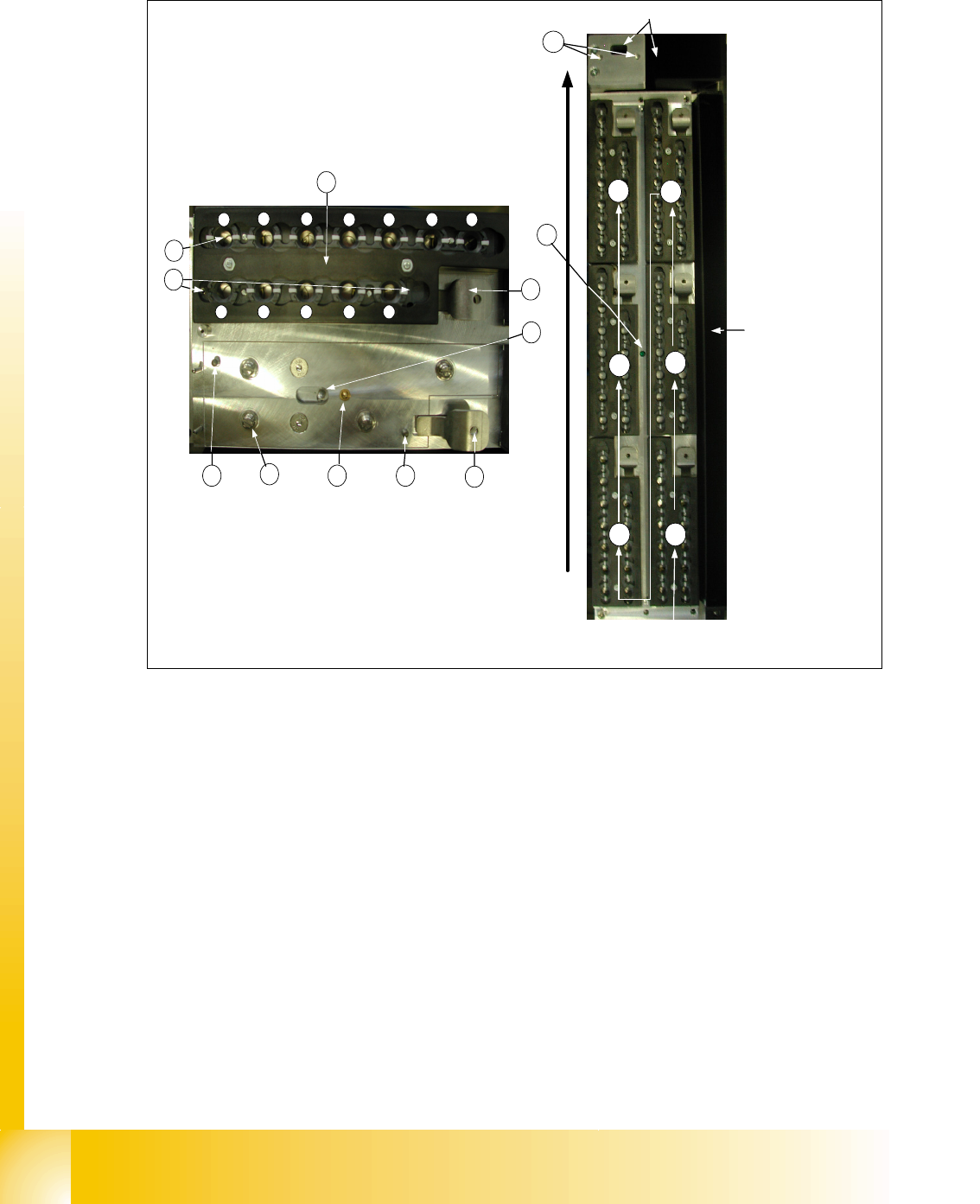
Fig. 8.5 - 2 Detail view of nozzle changer 20 segment C&P head
Legend left picture in Fig.8.5-2
(1) X/Y position of calibration fiducial (2) Locking plate
(3) Nozzle garage (4) The parallel pins to the centering maga-
zine
(5) Microswitch for magazine recognition (6) Tipping over lever to remove the magazine
(7) Locking Pin of magazine (8) 4 push button to the mount on the nozzle
changer carrier
(9) green LED check for a right mount of all
magazines on the nozzle changer carrier
(10) X/Y position of calibration fiducial of
nozzle reject box
conveyor direction
1
2
3
4
5
6
way of counting of the
magazines
nozzle reject box
component reject box
1
2 3
4 5 6 7
8 9 10 11 12
4
8
5 4
6
7
6
2
3
1
9
10
1 - 53
Student Guide SIPLACE X
Edition 09/2005 8 Collect&Place-Head 20
53
8.5.2.1 Nozzle reject unit
For the C&P 20 head reject unit we integreted a part to check and fixed the correct position of the
nozzle to the segment interface.
8.5.3 Adjustment of the height of the nozzle changer C&P 20 head
To get the correct safe distance between head (Component sensor) and nozzle changer is it nec-
essary to measure and adjust the height between mounting surface docking unit and the linear
guide of the X axis.
The distance have to
150,0mm +/-0,2mm. The support of the nozzle changer carrier has to be
adjusted with washers in its height until the the nominal distance is acchieved and then you can
mount the nozzelchangetr.
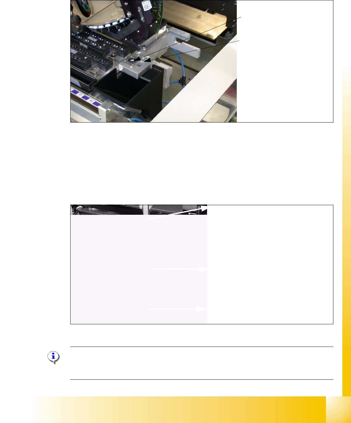
Fig. 8.5 - 3 Adjusting of nozzle changer at C&P20- head
Please Note for assembling the nozzle changer :
During assembling the nozzle changer keep attention that the component reject box can be easily
removed. Don´t use to long screws, otherwise the component reject box will be fixed.
Nozzle reject unit
Check the nozzle to the segment
interface
Reject nozzles
The height of the nozzle reject
unit have to adjust at
140,0 +\-
0,3 mm. The measurement pro-
cedure is the same like the
nozzle changer (see image be-
low).
Calliper
Top edge of the below linear guide
X-Axis
Mounting surface of the nozzle chan-
ger.
150,0mm +/-0,2