SiplaceX4_en.pdf - 第484页
1 - 16 S tudent Guide SIPLACE X 10 Modular conveyor Edition 09/2005 16 Fig. 10.2 - 6 Lifting t able Procedure to connect the t ables: ➠ The sleeve shaft is connected with the piston rod ( 1)of the pneumatic cylind er . T…
1 - 15
Student Guide SIPLACE X
Edition 09/2005 10 Modular conveyor
15
10.2.2.1 Procedure to widen the conveyor to single conveyor mode:
➠ Use SITEST (505) transport menu ’options and configuration’ ’widen conveyor’ to widen conv.
➠ The conveyor rails of conveyor 2 (right side fixed (track 1 left side fix)) are moved to the limits.
➠ The SITEST SW ask for connecting the lifting tables.
To widen conveyor from standard width allow up to 380 mm wide boards (see chapt.chapt.10.2.3)
- in combination with X4/X3/X2-machines.
To widen conveyor from extended width allow up to 450mm wide PCBs (see chapt.10.2.3) for pure
HF- and X-lines.
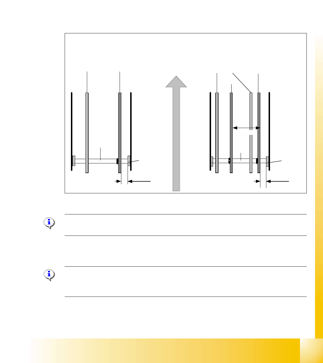
Fig. 10.2 - 5 Setting: "Fixed conveyor rail" SIPLACE HF on ’Standard width’ for X4/X3/X2-combinations
Please Note: he fixed conveyor rail should be adjusted only by SITEST software.
with the aid of the drivers .This ensures that the conveyor runs straight.
10.2.2.2 Connect Lifting tables at the Dual Conveyor
Please Note:
This option is only a mechanical function when you use the dual conveyor as an single conveyor.
The two lifting tables move parallel when they are connected.
➠ Remove lifting table plate: track 2 at placement area 1 and track 1 at placement area 2.
conveyor rails
movable fixed
Dual conveyor
conveyor rails
track 2 track 1
Shaft
support
Single conveyor
Direction of PCB transport
movable
fixed
fixed
43mm 38,8mm
251.7 mm
Shaft
Shaft
support
Shaft
1 - 16
Student Guide SIPLACE X
10 Modular conveyor Edition 09/2005
16
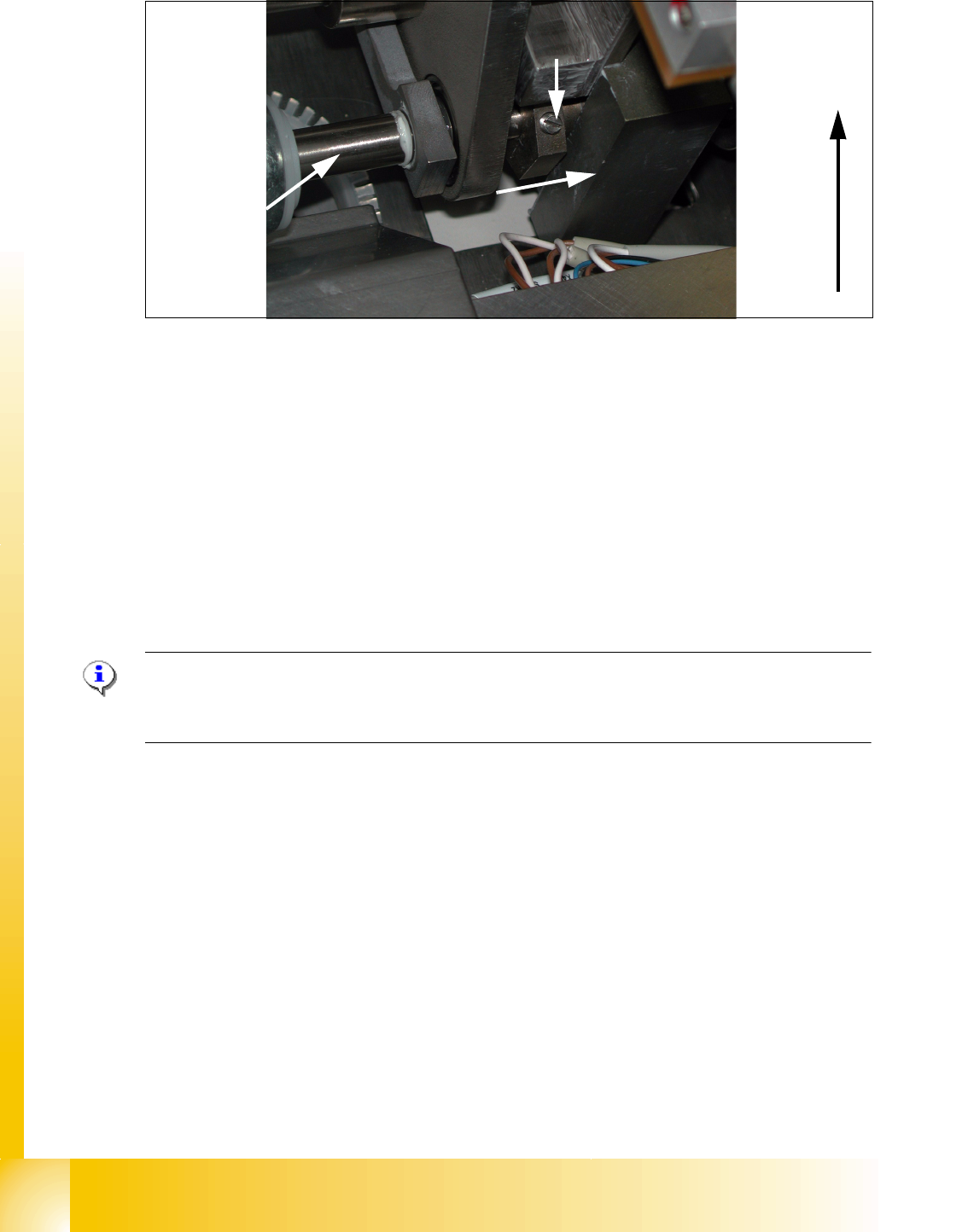
Fig. 10.2 - 6 Lifting table
Procedure to connect the tables:
➠ The sleeve shaft is connected with the piston rod (1)of the pneumatic cylinder. This shaft cou-
ple the second lifting table of the dual conveyor. At this shaft is a hexagon ring with 2 fixing
screws(4). They secure the sleeve shaft in the desired position.
➠ Transport direction (2)
➠ connecting direction (3): loose secure screw(4) and move sleeve shaft to the other shaft
➠ With a screw driver you can push the hexagon part onto the shaft of the lifting table 1.
➠ Do this for Lifting tables in all placement areas. (lifting tables in the PA’s 180° turned.)
➠ Configure the new transport mode at SIPLACE PRO 2.0
Please Note:
Best to connect is without pressure air supply to the lifting table.
This function is supported with Siplace Pro 2.0.
10.2.2.3 Procedure to put back single conveyor mode:
➠ Use SITEST (505) transport menu ’options and configuration’ to put ’widen conveyor’ back to
standard.
➠ The moveable conveyor rail of conveyor 1 (right side fixed (track 1 left side fix)) is moved to a
small conveyor width.
➠ The SITEST SW ask to disconnect the lifting tables - Do so-.
➠ The SITEST SW move now with transportcontroll SW the fixed rail of conveyor 2 (right side
fixed (track 1 left side fix)) back to the standard position.
➠ Now adjust conveyor width of both tracks to desired values.
1
2
Lifting table of
conveyor track 2
3
4
1 - 17
Student Guide SIPLACE X
Edition 09/2005 10 Modular conveyor
17
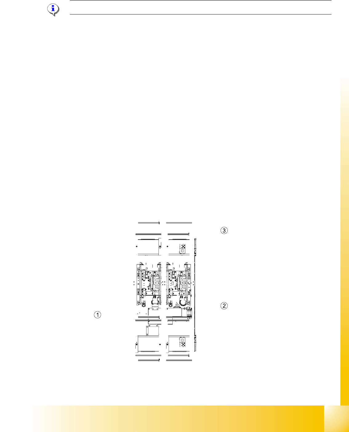
10.2.3 Move fixed conveyor rail for ’extended conveyor’
Please Note: This mode of a flexible conveyor at HF/X is available at single or at dual conveyor.
The standard position of fixed conveyor rail(s) are defined according the settings of X4- / X3- and
X2-machines. Because of the space on pure HF-lines a single conveyor can have up to 509 mm
wide boards; a dual conveyor up to 250 mm on each track.
➠ Use SITEST (505 or higher) transport menu ’options and configuration’ and ’extend conveyor’.
➠ The fixed conveyor rail of conveyor 2 (right side fixed (track 1 left side fix)) remain at its position
➠ The ’fixed conveyor of track 1(right side fixed (track 2 left side fix)) is moved 34mm outside.
This allow the wider boards. The moveable side of track2 (track 1-left side fix) could be set now
to more than 216 mm wide boards.
10.2.4 Checking the limit switch position
➠ Check the minimum and maximum width and ensure that the conveyor rails are parallel.
Settings:
Minimum width:49.7 mm
Maximum width, single conveyor:508.5 mm
Maximum width, dual conveyor:250.5 mm (When the fixed conveyor rail is extended)
Maximum width, dual conveyor:216.5 mm (Standard)
Fig. 10.2 - 7 Position of the width adjustment and conv. rail limit switches (symbolic draw)