SiplaceX4_en.pdf - 第445页
1 - 13 S tudent Guide SIPLACE X Edition 09/2005 9 Component handling 13 Fig. 9.2 - 5 Positions of the docking unit Po r tal 1 Po rt al 3 Po r t al 4 T ransportrichtung Sip lace X 3 Po rt a l 1 Por tal 3 Po r t al 4 T ran…
1 - 12
Student Guide SIPLACE X
9 Component handling Edition 09/2005
12
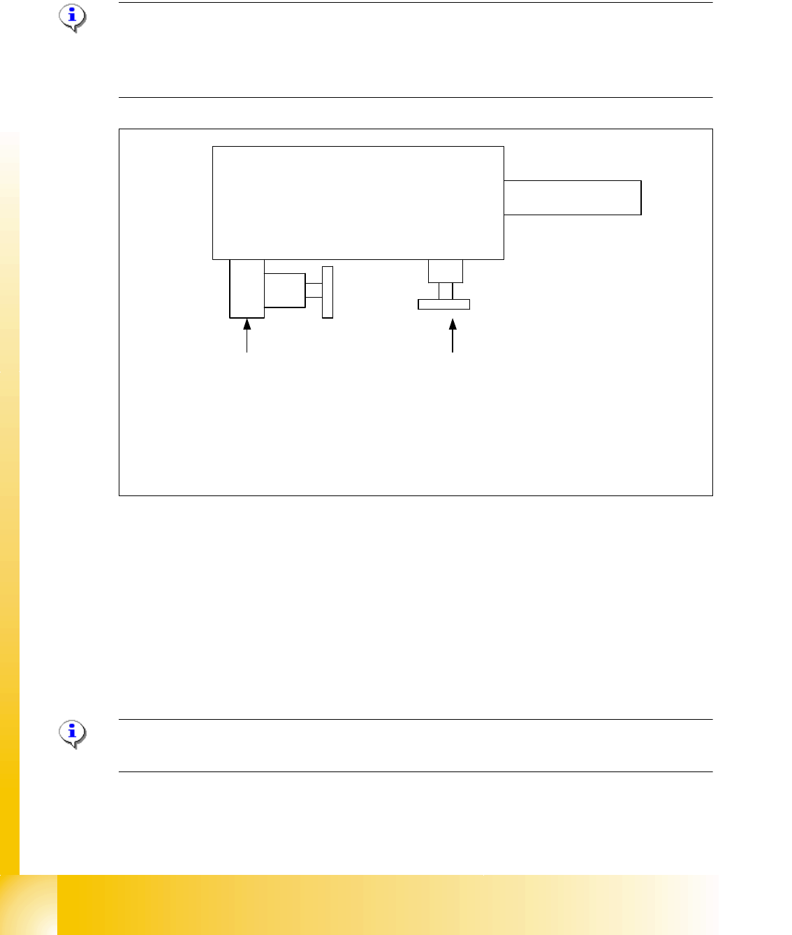
9.2.3.3 Adjustment pneumatic cylinder
The movement of the CAM-disks at the docking unit, left and right side can be individually adjus-
ted at the round cylinder
Note:
If you adjust the pneumatics cylinder is to be ensured that the COT is moved in parallel into the
docking unit. The docking and undocking procces of the COT should be set to
approx. 2 seconds.
Fig. 9.2 - 4 Adjustment the pneumatic cylinder on the docking unit
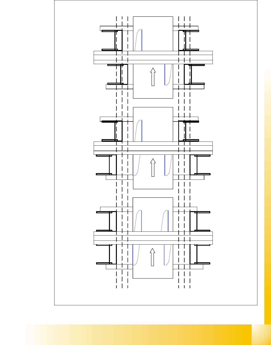
9.2.3.4 Position of the docking unit in the machine
The docking unit has three different mounting position in each location in the machine.
The position of the docking unit is depend on the machine type and thus of the number of gantries
in the placement area.
The docking unit of the MTC 2 is always installed in Position 3 (see Fig. 9.2 - 5).
Note:
For the option head modularity the position of the docking unit on both location are not changed.
Valve setting
Time characteristic for
docking the COT
Valve setting
Time characteristic for
undocking the COT
Pneumatic cylinder
Docking unit
Piston rod
Setting valve anticlockwise: Increase the time for the docking and undocking process
Setting valve clockwise: Reduce the time for the docking and undocking process
1 - 13
Student Guide SIPLACE X
Edition 09/2005 9 Component handling
13
Fig. 9.2 - 5 Positions of the docking unit
Portal 1
Portal 3
Portal 4
Transportrichtung
Siplace X 3
Portal 1
Portal 3
Portal 4
Transportrichtung
Siplace X 4
Portal 2
Portal 1
Portal 2
Transportrichtung
Siplace X 2
Position docking unit
3 2 1
Position docking unit
1 2 3
3 2 1
Position docking unit
1 2 3
Position docking unit
1 - 14
Student Guide SIPLACE X
9 Component handling Edition 09/2005
14
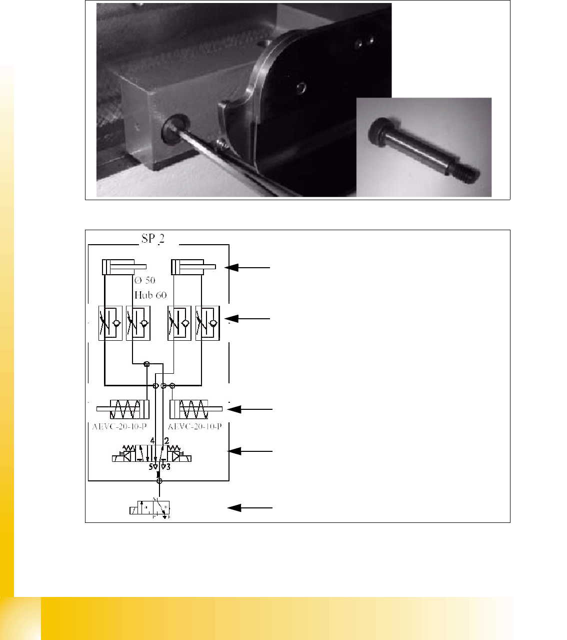
9.2.3.5 Mounting of Docking unit
The docking unit is fixed with a special screw to the machine so that the accuracy for picking up
of small components from the COT is guaranteed. These screw had to be fixed first before the
other screws when mounting the docking unit. (Necessary in case of changing the docking unit
COT to MTC 2 or vise versa).
Fig. 9.2 - 6 Special screw on the docking unit
Fig. 9.2 - 7 Pneumatic diagram docking unit
Pneumatic cylinder for move the cam disks. That
means the component table plate will move hori-
zontal 43mm and 20 mm vertical into the machine.
Throttle valves for adjust the speed of the pneu-
matic cylinders (Time adjustment). The time for ad-
just should be approx. 2-3 sec.for dokking and
undocking the COT. Check the time without COT.
Pneumatic cylinders for ejection the COT during
the undocking procedure.
5/2 Way valve for control the pneumatic cylinder.
Safety valve in case of electrical faults