SiplaceX4_en.pdf - 第603页
1 - 36 S tudent Guide SIPLACE X 13 MTC 2 Edition 09/2005 36 13.3.1.1 T erms of calibration lif ting axes Zero offset (zero position) The zero offset is used to define the refill position of cassette 1. The zero offset is…
1 - 35
Student Guide SIPLACE X
Edition 09/2005 13 MTC 2
35
13.3 Calibration MTC 2
13.3.1 Calibration sequence in general
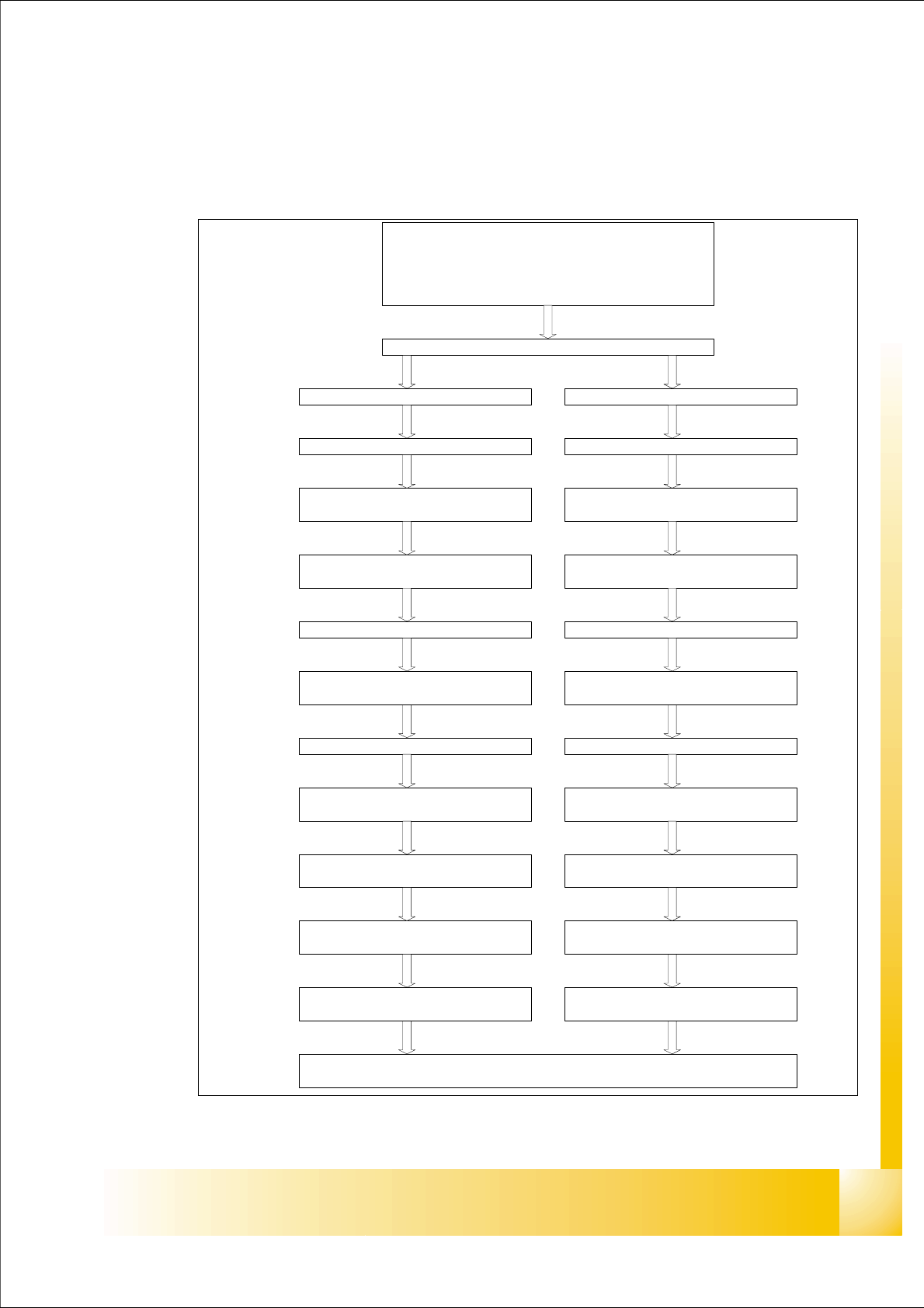
Fig. 13.3 - 1 General Calibration sequence
Preparation for Calibration
y Check the position MTC into the machine
y Set up the MTC with empty cassette
y set up a cassette in each lowest position from the magazine
y Start Sitest
Start: Reference run Machine / MTC
Tower 1 (XL) Tower 2
Lifting axis
Calibrate the zero point correction
(Zero Offset)
Calibrate the travel range
(max./min)
Lifting axis
Calibrate the zero point correction
(Zero Offset)
Calibrate the travel range
(max./min)
Feed axis
Calibrate the zero point correction
(Zero Offset)
Feed axis
Calibrate the zero point correction
(Zero Offset)
Calibrate the travel range
(max./min)
Calibrate the travel range
(max./min)
Calibrate the fiducial MTC 2
Calibrate refill position
Calibrate the transfer position
(Cassette 1-5)
Calibrate refill position
Calibrate the transfer position
(Cassette 1-4)
Calibrate the removal position
(FMT 1-5)
Calibrate the transfer position
Calibrate the removal position
(FMT 1-4)
Calibrate the transfer position

1 - 36
Student Guide SIPLACE X
13 MTC 2 Edition 09/2005
36
13.3.1.1 Terms of calibration lifting axes
Zero offset (zero position)
The zero offset is used to define the refill position of cassette 1. The zero offset is the difference
between the physical home position of the lifting axis and the refill position of cassette 1.
Refill positions (operator removal positions)
At the refill positions of cassettes 1 - 5 (tower 2: cassette 1 - 4), the cassettes can be removed
from the tower by the operator. The relevant cassette is located at the level of the tabletop which
is used as an aid in removal and feeding.
Transfer positions (WTC removal positions)
At the transfer positions of WTCs 1 - 5 (tower 2: WTCs 1 - 4) the lowest WTC in each cassette
can be moved onto the rails of the feed axis by the driver.
End positions (min. and max. position)
The end positions of an axis are reached when contact is made with the relevant limit switch. The
value determined here is used as a safety constraint when values are entered in the service menu
of the controller software.
Guide rails and stopper bars
The guide rails and stopper bars ensure that operation is only restored after refilling if the
cassettes and WTCs have been inserted correctly. They prevent them from inadvertently straying
out of the locked position during operation.
Cassette guide rails
The cassette guide rails guide cassettes onto the tabletops during refilling.
WARNING
Incorrectly set machine data can result in a crash between the lifting and feed axes or at the limit
positions of these axes.
1 - 37
Student Guide SIPLACE X
Edition 09/2005 13 MTC 2
37
13.3.1.2 Terms of calibration feed axes
Zero offset (zero position)
The zero offset is used to define the removal position of WTC 1. The zero offset is the difference
between the physical home position of the feed axis and the position of the driver at which it is
inserted in the WTC on level 1.
Removal positions (WTC removal positions)
At the removal positions of WTCs 1 - 5 (tower 2: WTCs 1 - 4), the driver can be inserted into the
lowest WTC in each cassette and move this into the transfer position.
Transfer position (component transfer position)
The transfer position is the position of the feed axis at which components can be picked up by the
placement head of the SIPLACE station without a correction value. The position of the reference
edges of a waffle pack tray in relation to the reference holes of the MTC 2 is stored in the line
computer.
End positions (min. and max. position)
The end positions of an axis are reached when contact is made with the relevant limit switch.
The value determined here is used as a safety constraint when values are entered in the service
menu of the controller software. If a limit switch is overrun during operation, the relevant axis is
stopped immediately to prevent a crash from occurring.
Handle sensor, WTC safety query and crash light barriers
The handle sensor checks the handle of the WTC in the removal position and thus the position of
the WTC which has been moved back, to prevent a crash from occurring.
The WTC safety query checks the correct position of the WTC which has been moved back before
the lifting axis is moved, to prevent a crash from occurring.
Depending on the height of the waffle pack tray which has been set up, the crash light barriers
check the height of the WTC which is moving back, to prevent a crash from occurring in the
cassette.
Disengaging mechanism
The disengaging mechanism enables the driver to engage with and disengage from the WTC.
WARNING
Incorrectly set machine data can result in a crash between the lifting and feed axes or at the limit
positions of these axes.
NOTE
For the calibration the zero point correction and transfer position at the feed axis please look to
the following notes on the next pages.