SiplaceX4_en.pdf - 第380页
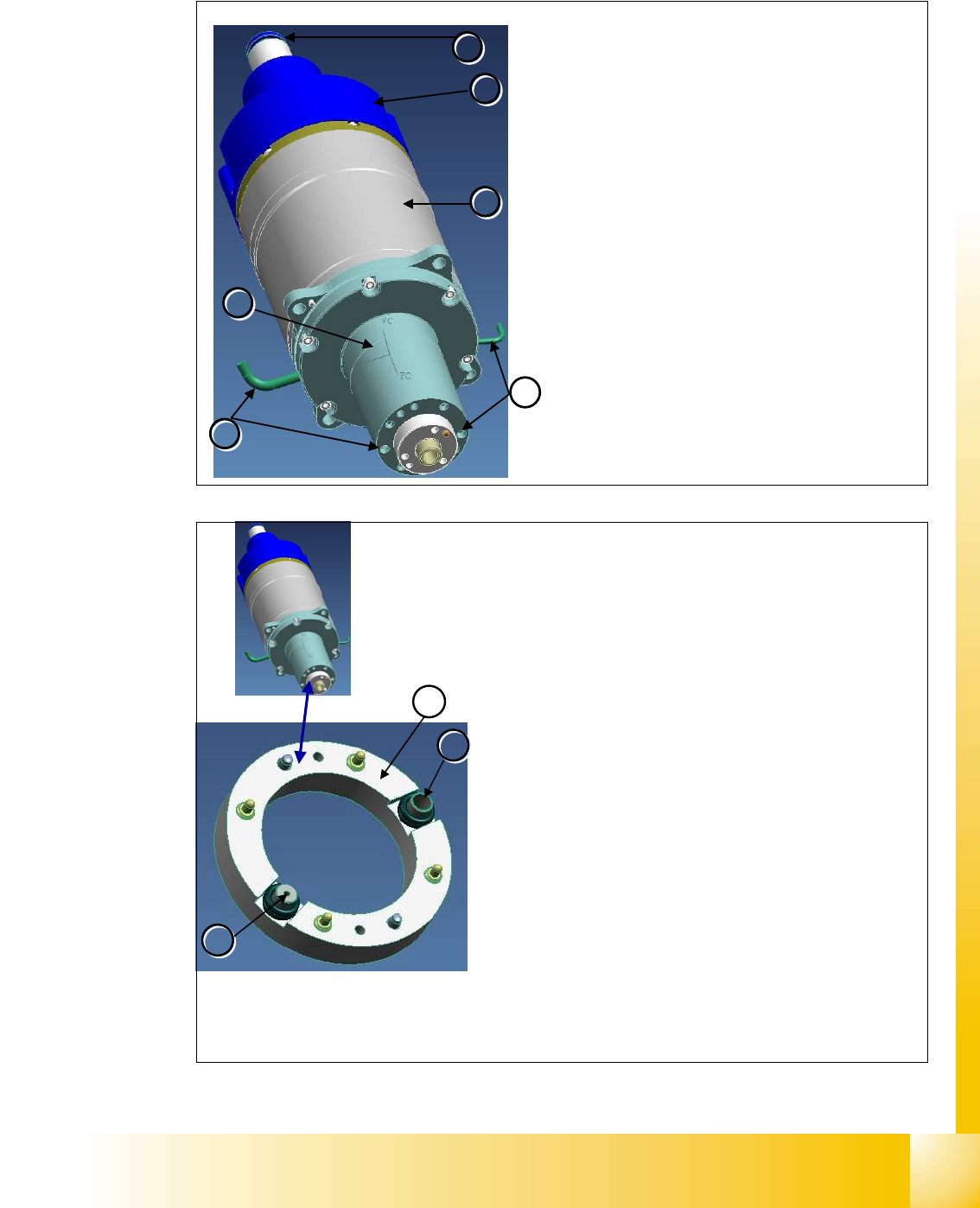
1 - 14 S tudent Guide SIPLACE X 8 Collect&Place-Head 20 Edition 09/2005 14 8.1.3.8 Component camera 8.1.3.9 Nozzle Changer 1 2 3 Component Camera (T ype 23 digit al) The compo nent camera is f ixed to th e C&P20 …
1 - 13
Student Guide SIPLACE X
Edition 09/2005 8 Collect&Place-Head 20
13
8.1.3.7 Star Drive
5
4
6
6
1
1
2
2
3
3
5
5
Star Motor
The star motor has a brushless three-phase drive
with integrated measurement system.
The motor shaft has a hollow design. This enables
compressed air to be supplied to the holding circuit of
the 20 segments.
Vacuum in the holding circuit is measured via the con-
nection
(4).
Air kiss and vacuum in the pickup/placement circuit is
measured via the connection
(5).
The star motor is not a spare part.
Star Motor Details
– 3-phase drive (1)
– Incremental measurement system (2)
– Compressed air connection for hold circuit (3)
– Flange on the motor shaft (6).
1
2
2
3
3
– The star motor is a brushless three-phase drive with si-
nus commutation.
– An optical measurement system is used for both commu-
tation and recognition of the rotary angle.This supplies
the track signals A, B and the zero pulse.
– The motor is controlled with the help of these track sig-
nals. The actual values of the position are evaluated on
the axis controller.The servo unit enhances perfor-
mance and is supplied with 2-phase current from the
axis card. (third phase is a calculated value)
– A flange is installed on the motor shaft. This flange is
screwed to the star carrier. The smoothed distributor
disc
(1) is located between the flange and the star hou-
sing.
– The motor shaft has a 6 mm drilled hole through which
compressed air is supplied to the hold circuit. The
smoothed distributor disc enables vacuum and air kiss
to be measured in the hold circuit
(3) and placement/
pickup circuit
(2).
1 - 14
Student Guide SIPLACE X
8 Collect&Place-Head 20 Edition 09/2005
14
8.1.3.8 Component camera
8.1.3.9 Nozzle Changer
1
2
3
Component Camera (Type 23 digital)
The component camera is fixed to the C&P20 head
with 4 screws and can be replaced during service work.
Five levels are available for illuminating the compo-
nents.
Visual field: 8.2 x 8.2 mm
Resolution: 14.1 µm/pixels
Component spectrum 01005-2220 max. 6x6mm, Bare
Dies, Flip Chip
Component Camera Details
Optical system (1)
Fixture (2) to housing
Camera amplifier
(3)
1
2
Nozzle Changer (optional)
The nozzle changer has 6 magazines, each with 12
nozzle garages for individual configuration.
A maximum of 2 nozzle changer charrier can be in-
stalled for each C&P 20 head.
If the nozzle changer is returned, the height of the noz-
zle changer needs to be checked with a calliper.
Each magazine is recognized via a micro switch and in-
dicated by a green LED.
The functions and calibration are identical with that of
nozzle changers for DLM heads.
Nozzle Changer Details
Push down openers (1) for magazines
Bracket
(2) to hold nozzle during return to garage
1 - 15
Student Guide SIPLACE X
Edition 09/2005 8 Collect&Place-Head 20
15
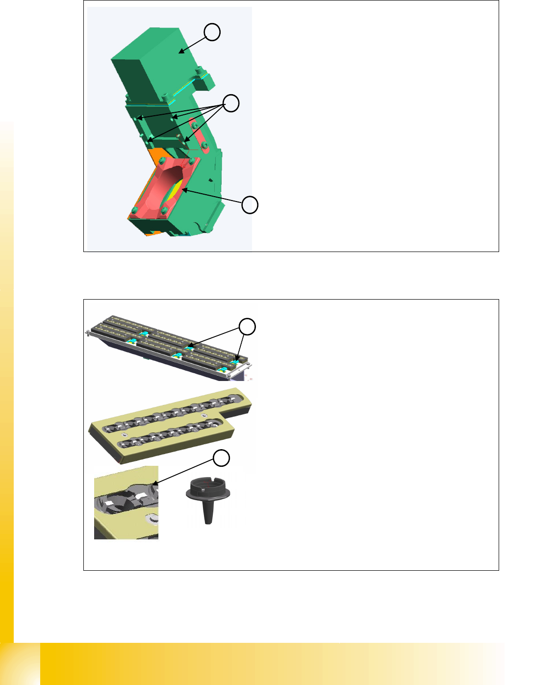
8.1.4 Pressure air supply DLM 2 C&P head
Fig. 8.1 - 3 Pressure air connectors C&P head
8.1.4.1 Holding circuit
(1) Pressure air connector for C&P-head Va-
cuum-holding circuit 4,7 bar Input pressure air
for the Placement head
(2) Pressure air connector for C&P-head Va-
cuum-pick up circuit with branching for the air
kiss supply 4,7 bar Input pressure air for the
Placement head
(3)-(5) Blind connector (Connector for Twin head)
Pressure air connector for cooling
X-Motor
Description Part No.
Venturi Block
-0X
O-Ring (6)
03011347-0X
1
1
2
2
3
3
4
4
6
6
5
5
Venturi Block
The venturi block consists of 20 small venturi nozzles
and is located behind the silencer.
Each venturi nozzle supplies one segment with vacuum
in the hold circuit.
If a segment is in the pickup/placement circuit, the hold
circuit vacuum is increased (for pickup) or eliminated
via air kiss (for placement).
Venturi Block Details
– Mounting (1) for star frame
– Mounting
(2) for silencer
– Venturi nozzle discharged air
(3) to the silencer
– Venturi nozzle vacuum outlet
(4) to the segments.
– Compressed air inlet
(5) to venturi nozzle The venturi
nozzle entrances have seals.
–O-ring
(6) between venturi block and silencer