SiplaceX4_en.pdf - 第176页
1 - 30 S tudent Guide SIPLACE X 4 Services to the machine Edition 09/2005 30 Note
1 - 29
Student Guide SIPLACE X
Edition 09/2005 4 Services to the machine
29
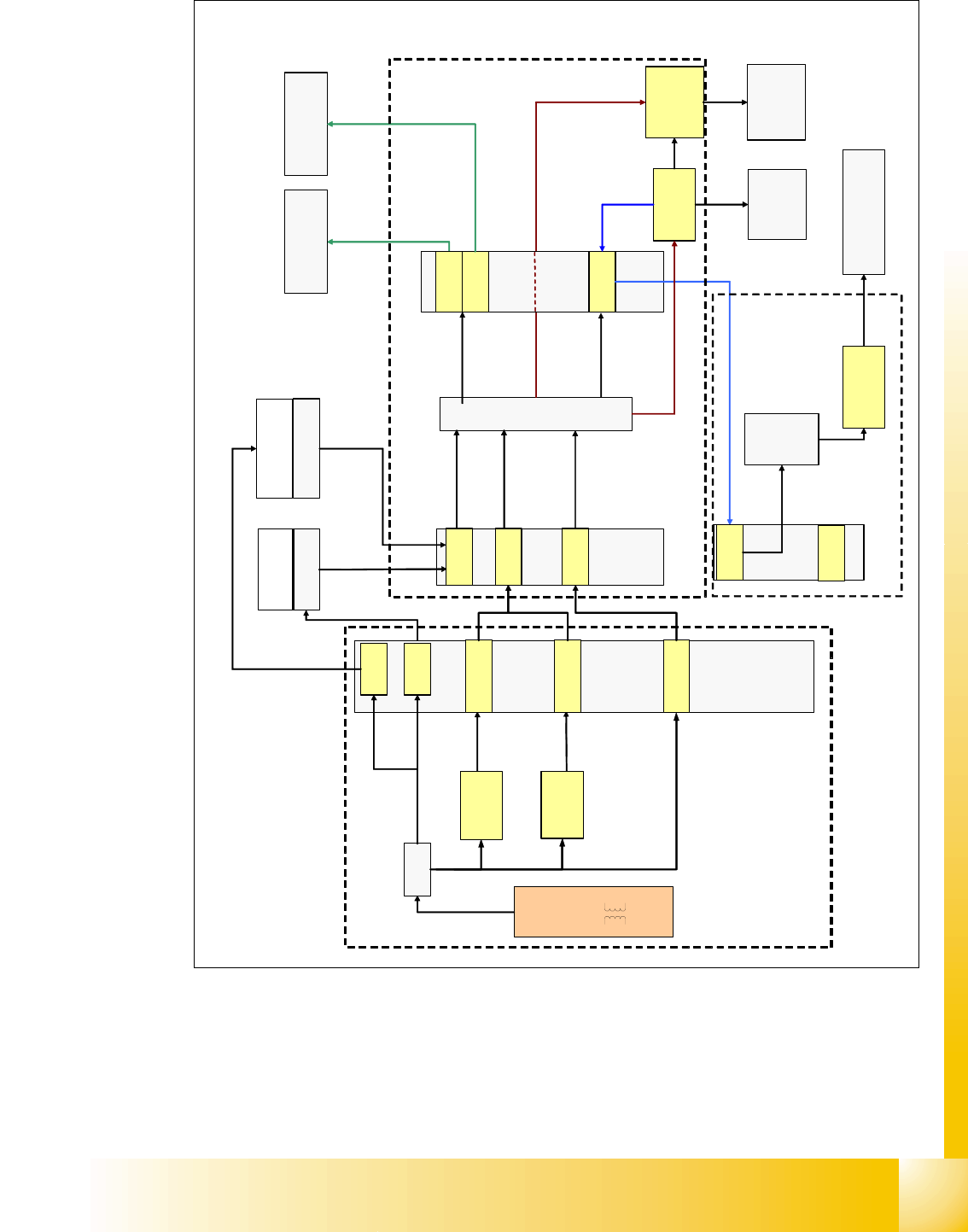
Fig. 4.2 - 21 power distribution
X
1
q
a
DC/DC
U20
DC/DC
U30
computer unit
axis unit 1
X16
X16
X13
24V
5V
sector 2
main
distrib.
X2qa
X4qa
X3qa
U7
+ 52V
T1
X18
section 4 sub distributor
X3ra
(24V, +/-15V, 5V, 3.3V)
(3.3 V not used)
placement
head 1
X5qa
X6qa
placement
head 2
X71qa
X71ra
+
/
-
1
5
V
+
/
-
1
5
V
,
3
,
3
V
5
/
2
4
V
24V +/-15V,
5V, 3,3V
DC/DC
vision
PCB
camera
gantry 2
5
/
2
4
V
5
/
2
4
/
4
2
/
5
2
V
5
2
/
4
2
V
5
/
2
4
/
4
2
V
DC/DC
distributor
X1ra
main
power
supply
distributor
vision
control
unit
+ 52V
5
V
+
/
-
1
5
V
4
2
V
FC/IC-
camera
gantry 2
5
/
2
4
V
5
/
2
4
V
5
2
/
4
2
V
PCB -camera
gantry 1
5
/
2
4
V
5
2
V
5
2
V
+ 52V
(1)
(2)
(3)
(5)
(2)
Legend:
1: main power supply distributor
2: connectors - main distributor section 2
3: sub-distributor section 4
4: terminal block X1qa section 2
5: terminal block X1ra section 4
3
.
3
V
X2
5
/
2
4
/
5
2
V
section 2 main distributor
main power supply
DC/DC
5/+-15V
DC/DC
3.3/5V/+-12V
(4)
1 - 30
Student Guide SIPLACE X
4 Services to the machine Edition 09/2005
30
Note

1 - 31
Student Guide SIPLACE X
Edition 09/2005 4 Services to the machine
31
4.3 Pneumatic System
4.3.1 In General
The air is supplied to the vacuum generator, which produces a vacuum using the venturi principle.
The venturi block actually consists of 2 separate venturi nozzles which produce vacuum for 2 cir-
cuits, the holding circuit and the pick up / placement circuit.
The level of vacuum produced is dependant on a number a factors the most obvious of which is
the condition of the venturi itself. Any leakage from or blockage within the system will result in
working inefficiently and therefore a reduction in the vacuum levels created. Therefore it is impor-
tant that the venturi is correctly sealed when reassembled and that the condition of the nozzles
within the system is good.
There are other factors that will affect the vacuum levels generated that are beyond your control.
The most significant of these is altitude. The higher above sea level a machine is located, the low
the ambient pressure in the room surrounding it is. Therefore at high altitude low vacuum levels
are created, an example is a machine in Munich, Germany at an altitude of 500m may generate
closed vacuum results of 870 mbar whereas the same machine as almost sea level in the UK
would generate vacuum results of 920mbar.
The other factor that can result in lower vacuum results is the weather. On a stormy rainy day a
low pressure system will be present and may result in closed vacuum results of 880 mbar. A week
later a bright sunny day results due to a high-pressure system. In this case closed vacuum results
of 900 mbar may result.
These 2 cases are only examples and no specific case / figures are used, but this just illus-
trateswhat can happen. In these cases it becomes even more important that the vacuum system
is well maintained and therefore performing efficiently.
A small PCB mounted on the head measures the vacuum pressure within the holding andpick up
/ placement circuits. Small tubes are attached to the back of the Collect & Place head that mea-
sure the circuit pressures at the vacuum distributor. These tubes are connected to pressure sen-
sors. The analogue outputs of these sensors are supplied to A/D converters. The resulting signals
are then sent via the CAN-Bus to the machine controller.