SiplaceX4_en.pdf - 第35页
1 - 1 1 S tudent Guide SIPLACE X Edition 09/2005 2 Overview 11 K2 Contactor (vo ltage built-up of the intermediate circuit volta ge for X/Y/S tar axes) 1, 3, 5 and 2, 4, 6 3 x 177 V AC K3 Contactor (vo ltage built-up of …
1 - 10
Student Guide SIPLACE X
2 Overview Edition 09/2005
10
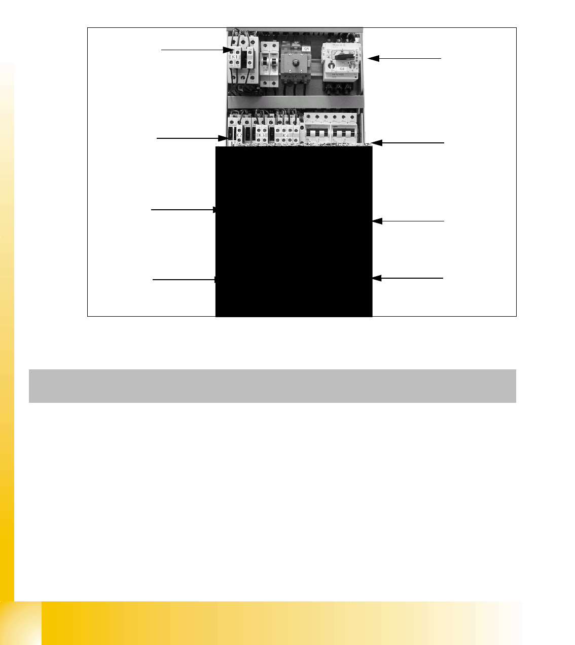
2.2.1 Power supply unit
The main power supply unit is mounted on a compact rack unit and located on the left side of the
middle section. When viewed from the outside, only the red main power switch is visible.
A lockable door prevents access to the unit.
2.2.1.1 Overview of Voltages in the Power Supply Unit
Fig. 2.2 - 2 Power supply at the front
K1
K2 / K3 / K4
K6
K5
F1/F14
F2 / F10 / F6 / F8 /
F12 / F13
F4 / F7
F11 / F5
Q1 / Q2
Component
assembly
Designation Contact Voltage
X100 Terminal strip for power supply L1, L2, L3 3 x 204 VAC / 3 x 380 VAC
3 x 400 VAC / 3 x 415 VAC
X102 Service socket 115 VAC / 220 VAC / 230 VAC / 240
VAC
Q1 Main switch 1, 3, 5 and
2, 4, 6
3 x 204 VAC / 3 x 380 VAC
3 x 400 VAC / 3 x 415 VAC
Q2 Motor circuit-breaker 1, 3, 5 and
2, 4, 6
3 x 204 VAC / 3 x 380 VAC
3 x 400 VAC / 3 x 415 VAC
K1 Main contactor 1, 3, 5 and
2, 4, 6
3 x 204 VAC / 3 x 380 VAC
3 x 400 VAC / 3 x 415 VAC

1 - 11
Student Guide SIPLACE X
Edition 09/2005 2 Overview
11
K2 Contactor (voltage built-up of
the intermediate circuit voltage
for X/Y/Star axes)
1, 3, 5 and
2, 4, 6
3 x 177 VAC
K3 Contactor (voltage built-up of
the intermediate circuit voltage
for X/Y/Star axes)
1, 3, 5 and
2, 4, 6
3 x 177 VAC
K4 Contactor (voltage built-up of
the intermediate circuit voltage
for X/Y/Star axes)
1, 3, 5 and
2, 4, 6
3 x 177 VAC
K5 Contactor ( software release is
ON)
A1 (+) – A2
(-)
1.2
3.4
5.6
24VDC
24 VDC
against ground
24 VDC against ground
24 VDC against ground
K6 (SSK) Contactor unit L+, X3, X5 24 VDC against ground
F1 Fuse for service socket; 1-pol. 1, 2 115 VAC / 220 VAC
230 VAC / 240 VAC
F2 Fuse for component table;
3-pol.
1, 3, 5 and
2, 4, 6
3 x 36 VAC
F4 Fuse for X-/Y-axis;
3-pol.
1, 3, 5 and
2, 4, 6
3 x 177 VAC
F5 Fuse for star axis;
1-pol.
1, 2 145 VDC
against ground
F6 Fuse for Z-/DP-axis; DP-drive
C&P20 head, 1-pol.
1, 2 39 VDC against ground
F8 Fuse for PCB conveyor;
1-pol.
1, 2 33 VDC against ground
F10 Fuse for rectifier V7 and V70;
3-pol.
1, 3, 5 and
2, 4, 6
3 x 39 VAC
F11 Fuse for inrush current limita-
tion board; 1-pol.
1, 2 33,6 VDC
against ground
F12 Fuse for illumination
1-pol.
1, 2 52 VDC against ground
F13 Fuse for monitor; 1-pol. 1, 2 26 VDC against ground
F14 Fuse for Y-motor fan; 1-pol. 1, 2 26 VDC against ground
Component
assembly
Designation Contact Voltage

1 - 12
Student Guide SIPLACE X
2 Overview Edition 09/2005
12
2.2.2 Pneumatic unit
The pneumatic unit is mounted on a compact rack unit and located on the right side of the middle
section. A lockable door, which can be opened with the machine key, prevents access to the unit.
The pneumatic unit contains all electrical connections for the compressed air and transport control
systems. The transport control system with the SMEMA (Siemens) board interface facilitates the
transport of PCBs within the machine and to the previous/next stations.
Fig. 2.2 - 3 Pneumatic unit as rack unit
(1) Manual main shut-off valve
(2) Manometer for machine components
(3) Manometer for compressed air into the gantry distributor (0 - 0.6 MPa, 0 - 6 bar)
(4) Manometer for bulkcase feeder and nozzle changer
(5) Main input manometer
(6) Filter compressed air
(7) Screw, for opening and pulling out the pneumatic unit
(8) Transport control with connections to previous and next stations
8