SiplaceX4_en.pdf - 第129页
1 - 59 S tudent Guide SIPLACE X Edition 09/2005 3 Communication and Control 59 3.5.3 One wire Bu s Siplace X machine The structure of the One Wire Bus Siplace X was changed in opposite the HF/HF3 machine. With the new ha…

1 - 58
Student Guide SIPLACE X
3 Communication and Control Edition 09/2005
58
6. CAN Bus Commands for the status reject box nozzles 3
– command: 6a 32 04
6a 32 --> command for status reject box nozzles
04 --> gantry 4
- Click on the "Send" button.
– Acknowledge: 6a 00 00 --> reject box is present
6a 00 01 --> reject box not present
Note: The reject boxes will check via the message loop. That mean, at first you have to close the
whole securitey loop (table, cover,...) before the software check the state of the message loop.
(the image on the station after you press the start button), (e.g.missing reject bins). 3
7.CAN Bus Commands to check both temperature sensors 3
– command: 6e 11 01 01 28 10
6e 11 --> command
01 --> not def.
01 --> Gantry 1
28 --> subsystem temperature
10 -->temperatuer sensor on top of the headplate(16)
- Click on the "Send" button.
– Acknowledge: 6e 00 1c 4b
6e 00 --> command OK
1c --> temperature 1c hex-->28°C
– command: 6e 11 01 01 28 11
6e 11 --> command
01 --> not. def.
01 --> Gantry 1
28 --> Subsystem temperature
11 -->temprature sensor on bottom of the headplate(17)
- Click on the "Send" button.
– Acknowledge: 6e 00 1d 4b
6e 00 --> command OK
1d --> temperature 1d hex-->29°C
8. CAN Bus Commands for initialization the one wire bus 3
– command: 3d 01
3d 01 --> command for initialization
- Click on the "Send" button.
– Acknowledge: 3d 00 01 Initialization successful
1 - 59
Student Guide SIPLACE X
Edition 09/2005 3 Communication and Control
59
3.5.3 One wire Bus Siplace X machine
The structure of the One Wire Bus Siplace X was changed in opposite the HF/HF3 machine.
With the new hardware structur of the bus system the allocation of subsystems to the hardware
components is different (see table).
Attention: New Application on the I/O moduls necessary! (BIOS E0100323, Application E0110350
or higher)
During the initialization procedure all subsystems send a message via the public byte by yourself.
The public byte comes from each subsystem of the machine via the CAN ID +3hex. If the state of
a subsystem changes, the subsystem reports automatically and without request of the application.
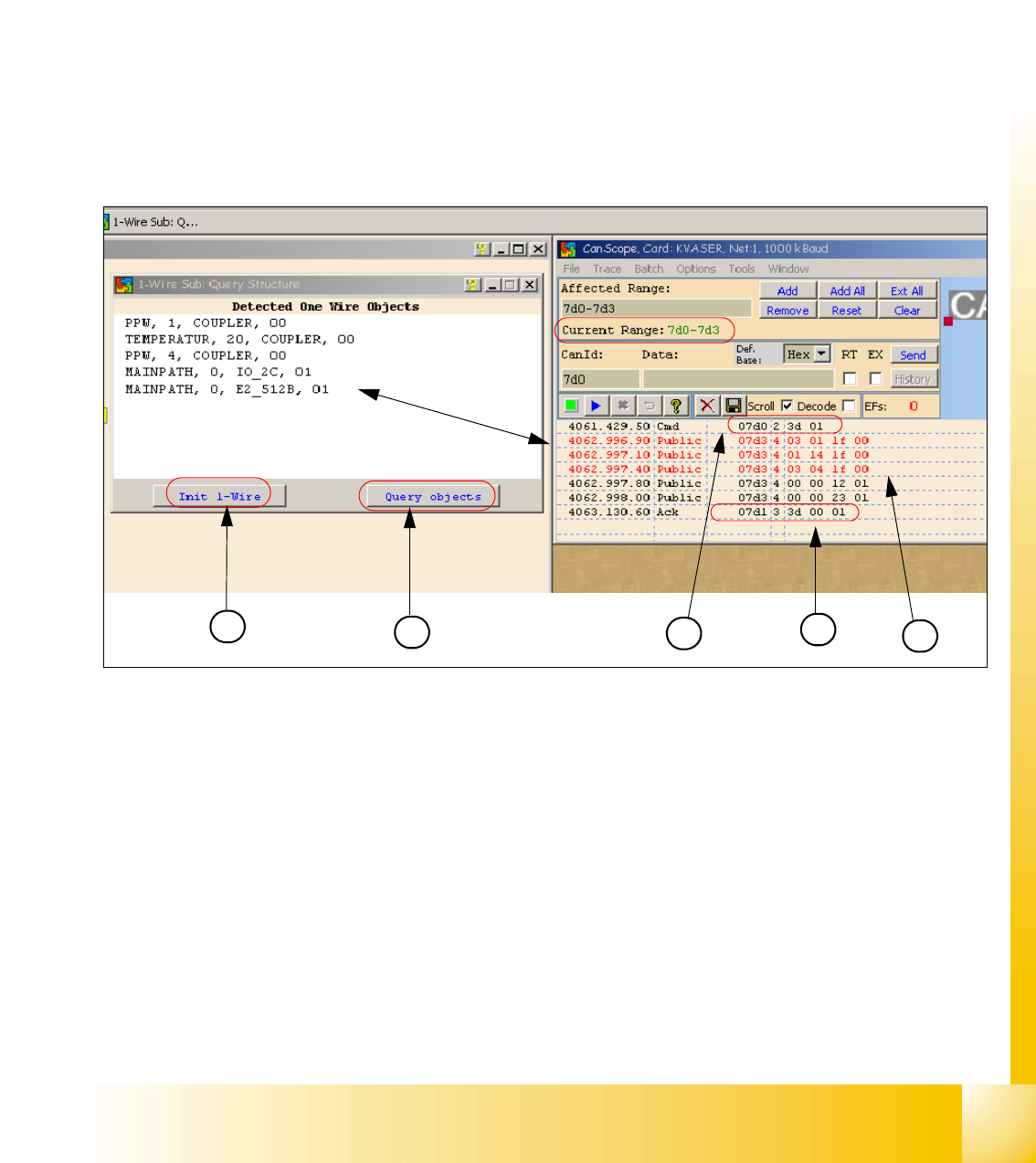
3.5.3.1 Communication One Wire
Fig. 3.5 - 18 Communication with the one wire Interface RS232 on the I/O module
(1) "Init 1 Wire" send the command via the CAN ID 7d0 for PA1.
(2) Query objects shows the decoded Public Bytes.
(3) Net window: 07d0 3d 01 command Initialization of the One Wire Bus.
(4) 5 Public bytes from the Subsystem RS232 Interface on the I/O module
1. 03 01 1f 00 --> 03 Subsystem NC / 01 Gantry / 1f Coupler
2. 01 14 1f 00 --> 01 Subsystem Temperature Gantry(1/4) / 14 1k EEPROM / 1f Coupler
3. 03 04 1f 00 --> 03 Subsystem NC / 04 Gantry / 1f Coupler
4. 00 00 12 01 --> 12 I/O component and EEPROM
5. 00 00 23 01 --> 23 4k EEPROM
(5) Acknowledge (Answer) Command CAN ID +1hex --> 3d 00 01
1
2
4
3
5
1 - 60
Student Guide SIPLACE X
3 Communication and Control Edition 09/2005
60
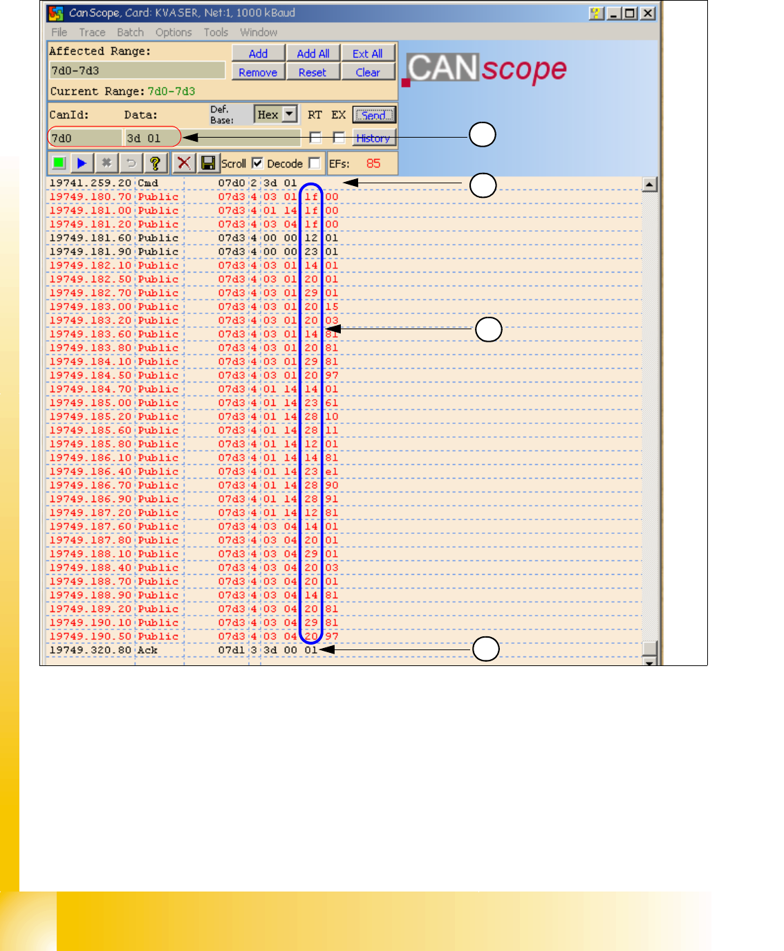
3.5.3.2 Overview Initialization of the One Wire Bus
(1) CAN BUS command for initialization
(2) CAN BUS command sent.
(3) Subsystems give a message via the public bytes
1f --> Coupler 12 --> I/O component with EEPROM 14 --> 1k EEPROM
20 --> 4 channel A/D 23 --> 4k EEPROM 28 --> Temperature
29 --> 8 x I/O component
(4) Answer initialization successful.
1
2
4
3