SiplaceX4_en.pdf - 第538页
1 - 33 S tudent Guide SIPLACE X Edition 09/2005 1 1 Sitest 33 ➠ PCB mapping is running. ➠ Then the gantry axes move the camera up to the start position. This is centered according to the synthetic picture of the bright c…
1 - 32
Student Guide SIPLACE X
11 Sitest Edition 09/2005
32
11.2.15 PCB mapping
With the PCB mapping the linearity of the X- and Y-guidance for PCB-camera movement is mea-
sured in the placement area.
The PCB-camera center the cross fiducials on a high precise glass plate. This glass plate is cali-
brated with a measurement machine and this data´s are considered in the measurement se-
quence.
Preperation mapping: 11
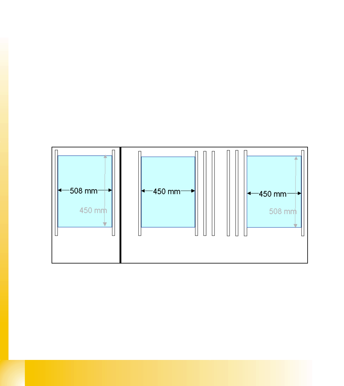
➠ At the single conveyor the SITEST move the transport rails to 508mm wide the mapping plate
is 90 degree turned.
➠ At dual conveyor the SITEST SW move all the transport rails depend of the conveyer which
is selected the conveyor for mapping to 450 mm wide the other track to 0mm. This allow to
used the Dual conveyor as a single conveyor. The Mapping must be carried out for the maxi-
mum conveyor width.
➠ To prepare the PCB and RV Mapping the SITEST SW move automatically the conveyer rails
that the mapping plate fit to the the referring track.
➠ The C&P6/12 Heads have to have 956 nozzles, the C&P20 head 1235 nozzles and the Twin
head 517 nozzles for mapping.
➠ The calibration tools are in the calibration pocket.
Fig. 11.2 - 17 Position mapping plate and conveyor rail position for single and dual conveyor
Procedure: 11
➠ insert the mapping disk at the station computer to prepare and copy the nominal data for this
individual mapping plate.
➠ Put the mapping plate in the input conveyor for placement area 1 or in the intermediate con-
veyor for placement area 2.
➠ Now appears the teach menue to teach the fixed PCB corner OK.
Single conveyor
Dual conveyor
Track 2 Track 1
1 - 33
Student Guide SIPLACE X
Edition 09/2005 11 Sitest
33
➠ PCB mapping is running.
➠ Then the gantry axes move the camera up to the start position. This is centered according to
the synthetic picture of the bright cross structure at this position.
➠ This results are set for the nominal coordinates. 40.000 µm in X- respectively Y- direction
added for the next fiducial nominal position.
➠ The deviation of the structure to this theoretical position is measured.
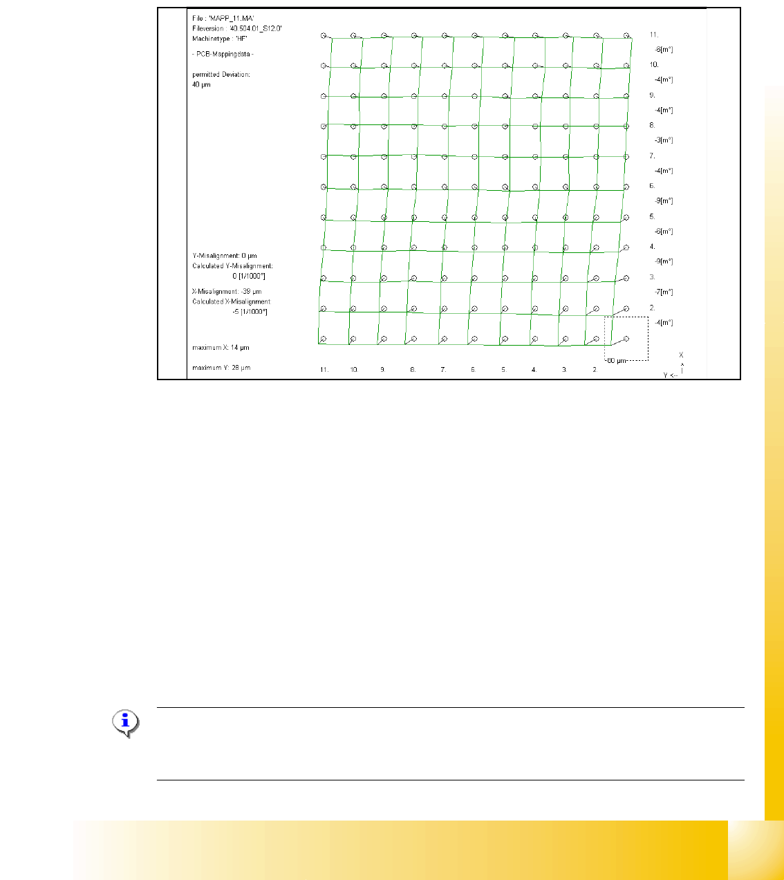
Fig. 11.2 - 18 Result of PCB mapping
The result are saved in the mapp _xy.ma ( x= number of the gantry , y= transport track)
11.2.16 Head mapping( C&P,Twin head)
With the head mapping the linearity of the X- and Y-guidance for C&P head movement is mea-
sured in the placement area.
The C&P head place the calibration tool on the mapping glass board exact to the nominal posi-
tions of the glass plate. The PCB-camera measure the placement accuracy of this placements for
the whole placement area.
➠ After the PCB mapping the placement head place at the theoretical positions of the PCB-map-
ping the calibration tool.
➠ The PCB-Camera look for the placement accuracy on the 4 fiducials at the calibration tool cor-
ner.
Note:
All described automatically calibration steps above, can you do manually step by step under the
sub menus (see chapter 12.1).
1 - 34
Student Guide SIPLACE X
11 Sitest Edition 09/2005
34
11.2.17 New function in the Sitest program
11.2.17.1 Menu of transport
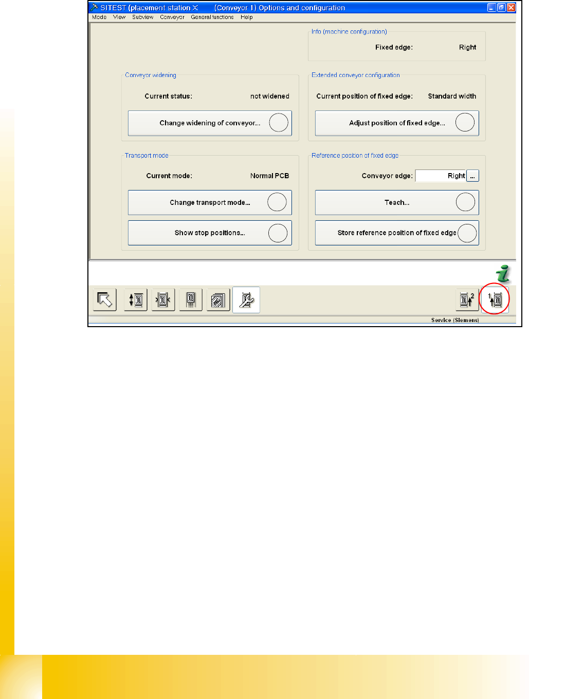
Fig. 11.2 - 19 Transport - option and configuration
a Change widening of conveyor (only track 1 for dual conveyor):
It appears a next menu, in which you can choose "widened" or "not widened" (Standard width).
Widened that means, you configure your dual conveyor as an single conveyor. Track 2 will be
move together (limit switch). The fixed conveyor rail (Track1) has the same position like before.
If you choose the point 4 at first (Excess width) a max. width of 450 mm is possible.
s Change Transport mode:
This function do you need to configure the long board option.
Next menu: normal PCB/ long PCB
d Show Stop positions:
shows the number of position in PA 1 and PA2, additional the offset depend on the standard
position (PCB Reference- corner). The offset of the long board option will be send by Siplace
Pro.
f Here you can move the fixed conveyor rail in his standard positon for standard width and Ex-
cess width (Values are from the Machinendata of the transport control board). Excess width
that means, the fixed conveyor rail will be move 34mm more outside (Dual conveyor Track1
and 2= 250mm, flexible dual conveyor Track1= 450mm, Single conveyor =508mm).
g Point 5 and 6 only with Siemens Service Passwort active! You can teach the fixed conveyor
rail (left, right).
h Save the teach data from point 5.
1
2
3
4
5
6