SiplaceX4_en.pdf - 第320页
1 - 4 S tudent Guide SIPLACE X 7 T win-Head Edition 09/2005 4 7.1.1 T echnical Dat a T win- Head Fig. 7.1 - 2 T e chnical data TWIN- head Placement accuracy (X/Y) 35µm by 4sigma with IC-camera Placement accuracy (X/Y) 30…
1 - 3
Student Guide SIPLACE X
Edition 09/2005 7 Twin-Head
3
7 Twin-Head
7.1 Overview
The TWIN-head consists of two P&P heads of same model coupled together, who work according
to the Pick&Place principle. The second P&P head is rotated 180 degrees. For the TWIN-head,
new nozzles (Type 5xx) were developed. However, the nozzles of the Pick&Place head type 4xx
and the nozzles of the Collect&Place heads type 8xx and 9xx we can use with an adapter.
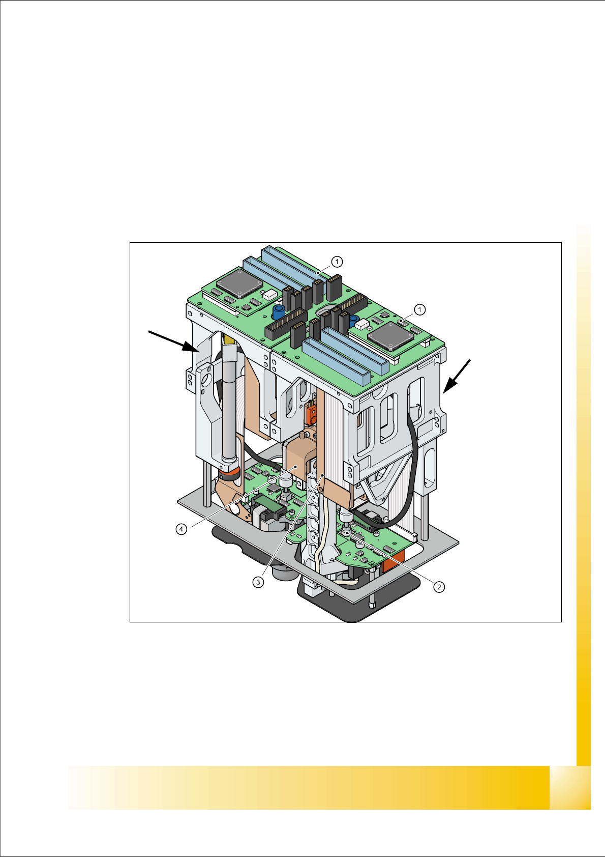
Fig. 7.1 - 1 TWIN- head
1. Main board on modul 1 and modul 2
2. D-Axis
3. Linear motorZ-Axis
4. Incremental measurement system Z-Axis
Modul 1
Modul 2, rotate 180 °
concerning Modul 1.

1 - 4
Student Guide SIPLACE X
7 Twin-Head Edition 09/2005
4
7.1.1 Technical Data Twin- Head
Fig. 7.1 - 2 Technical data TWIN- head
Placement accuracy (X/Y) 35µm by 4sigma with IC-camera
Placement accuracy (X/Y) 30µm by 4sigma with FC-camera
Placement accuracy (Angle) 0,07° by 4sigma
Placement speed 3500 cph
Maximum component size: 50 up to 40 mm single measurement on both segments
69 up to 10 mm multiple measurement by both segments
125 up to 10mm multiple measurement by one segment
200 up to 125mm multiple measurement with restriction
Max. component height 25 mm
Placement force 1-15 N
D-Axis / Resolution direct drive / 0,001 degree
Z-Axis / Resolution Linear motor / 0,5 µm
Travel range Z-axis app. 60 mm
Nozzle types 5xx (4xx, 8xx, 9xx with adapter)
Distance between the segments approx. 71,00 mm
Max. weight of component 100g
Option High Force Twin Head
Placement Force max. 30 N
1 - 5
Student Guide SIPLACE X
Edition 09/2005 7 Twin-Head
5
7.1.2 Parts on the Twin- Head
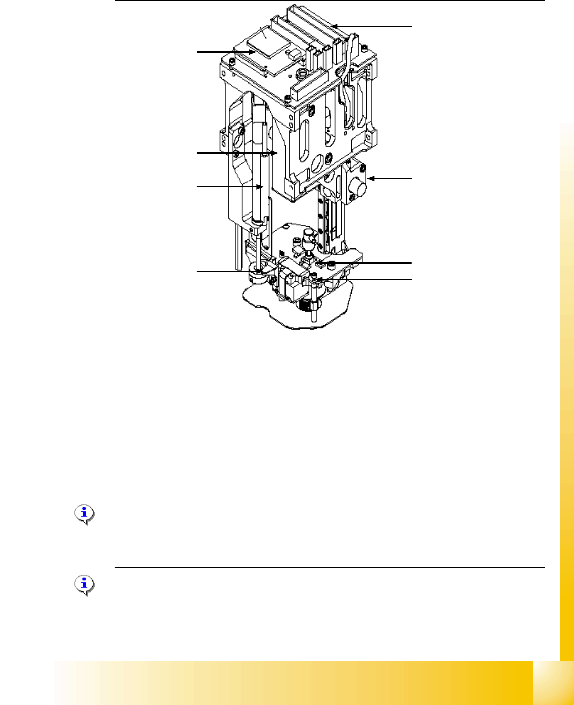
Fig. 7.1 - 3 Parts TWIN- head
1. CAN Bus Processor board ( not mounted, is now on the Head interface C500)
2. Main board TWIN- head
3. D-axis complete with incremental encoder and force sensor
4. Incremental encoder Z-axis
5. Retract unit to return the Z-axis in a safety area in case of power fail
6. Vacuum generator
7. Actuator retract unit (right) / Screw on the force measurement board (left)
Please Note:
Please use this two Positions (7) to move manually the Z-Axis downwards if the Servo board
switch off (Switch off the Axis card)!
Please Note:
The parts 1, 2, 4, 5 and 6 are spare parts and the whole module. ( Service manual).
4
3
2
5
1
6
7
7