SiplaceX4_en.pdf - 第78页
1 - 8 S tudent Guide SIPLACE X 3 Communication and Control Edition 09/2005 8 Compiling the pick-up position (X/Y coordinate s and angle) 3 following values are t aken into account for calculating the th eoretical pick-up…
1 - 7
Student Guide SIPLACE X
Edition 09/2005 3 Communication and Control
7
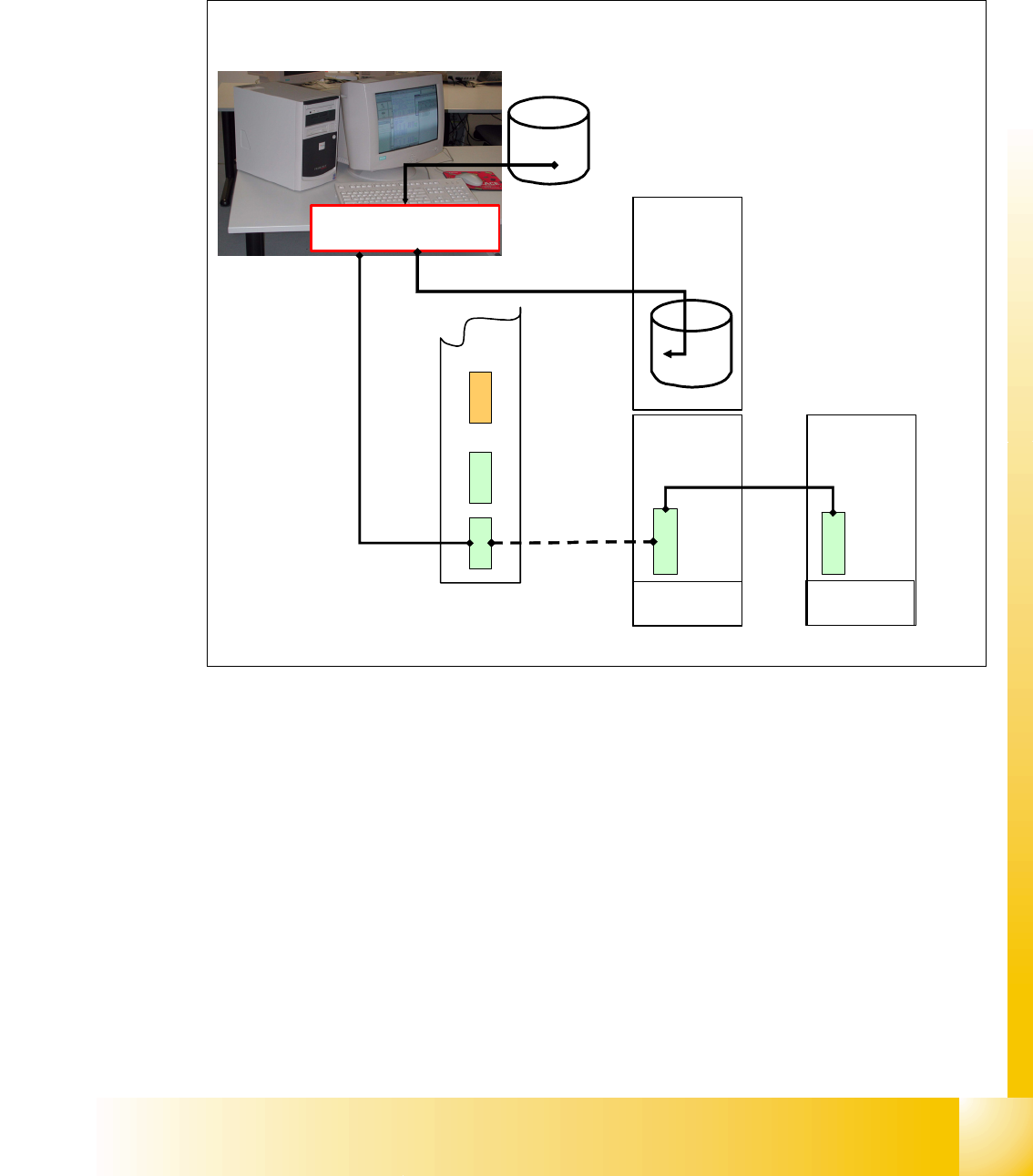
3.2.2 Computer at the LAN Network
The SIPLACE Pro programming computer read the files, which are required for production, from
the hard drive and compiles it. The compile run creates the required data format and send it to the
station computer. This data files are then saved on the hard drive at the station.
Fig. 3.2 - 2 computer at LAN network
compiled Line
computer data
Machine
Controller
Station
Computer
Data for placement
program
compile run of data used
for placement program
XXX.la
XXX.rs
XXX.gf
XXX.pm
...
aktuell.nu
aktuell.rs
XXX_12.gf
XXX_5.mk
...
Dual LAN Unit
1 - 8
Student Guide SIPLACE X
3 Communication and Control Edition 09/2005
8
Compiling the pick-up position (X/Y coordinates and angle) 3
following values are taken into account for calculating the theoretical pick-up position:
Compiling the placement position (X/Y coordinates and angle) 3
following values are taken in account for calculating the theoretical placement position:
• feeder table is on the left side or right side (0 or 180 degree)
• feeder track
• feeder pick-up position
• programmed pick-up offset
• offset from feeder table position calibration
• segment offset 1 of segment x
• segment offset 2 of segment x
Compile run
SIPLACE Pro
Compile run
station computer
Compile run
SIPLACE Pro
Compile run
station computer
• PCB angle in conveyor (how is the PCB in the transport,
0,90,180,270 degree?).
• PCB zero point offset
• placement position on PCB
• fixed PCB corner
• offset PCB - component camera
• segment offset 1
• segment offset 2
• mapping values
• fine calibration values
1 - 9
Student Guide SIPLACE X
Edition 09/2005 3 Communication and Control
9
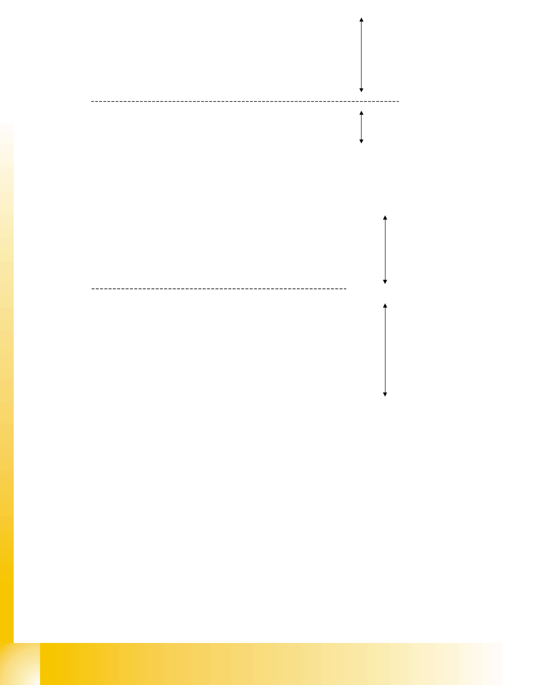
3.2.3 Communication on placement machine
The placement data files, stored at the hard drive, are compiled at the station computer. This com-
piling add the calibrated values, taken during calibration in Sitest, to the pick up and placement
data.
Fig. 3.2 - 3 communicaton on the station
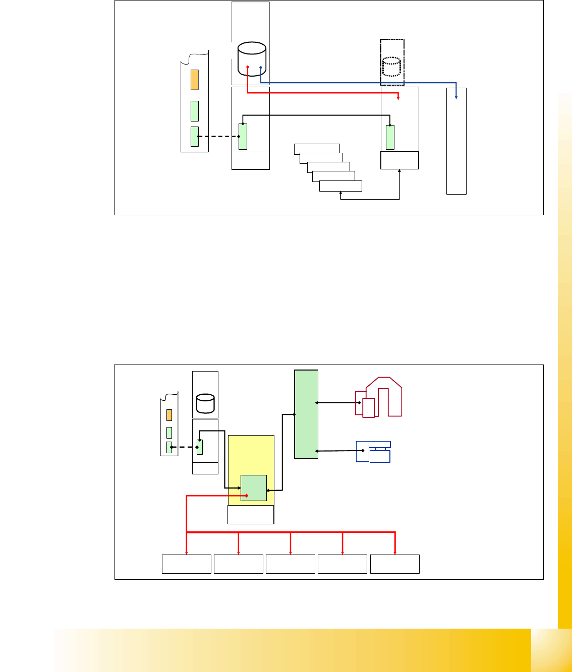
3.2.4 Machine Controller Communication
For the calculation of the ’pick up coordinates’ the MC add the pick up correction values (former
pick up offsets) to the pick up coordinates.
For the calculation of the
’placement coordinates’ the MC add the PCB position correction values
and the component correction values (from camera evaluation) to the placement coordinates.
Fig. 3.2 - 4 communication with MC
Axis controller
Axis controller
Axis controller
Axis controller
Machine
Controller
Station
Computer
Compiled
data LC
aktuell.nu
aktuell.rs
XXX_12.gf
XXX_5.mk
...
Compile
run SC
Stationcomputer with Visionsoftware
Visioncomputer for PA2 optionally
Axis controller
CAN BUS 1Mbit/s
X-Axis
controller
SC
Station computer
Machine
Controller
Y-Axis
controller
Star-Axis
controller
Z-Axis
controller
DP-Axis
controller
Placement
data at MC
target position for
pick-up / placement to axis
controller from MC
Dual LAN Unit
PCB camera
Component camera