SiplaceX4_en.pdf - 第296页
1 - 68 S tudent Guide SIPLACE X 6 Collect &Place-He ad 6/12 Edition 09/2005 68 Please Note: The adjustment for the reject circuit is not nece ssary on the HF/Siplace X machine. Please Note: Both forced air circuits a…
1 - 67
Student Guide SIPLACE X
Edition 09/2005 6 Collect &Place-Head 6/12
67
6.4.10.3 Adjustments of Air Pressure Values with the Compressed Air Testing Device
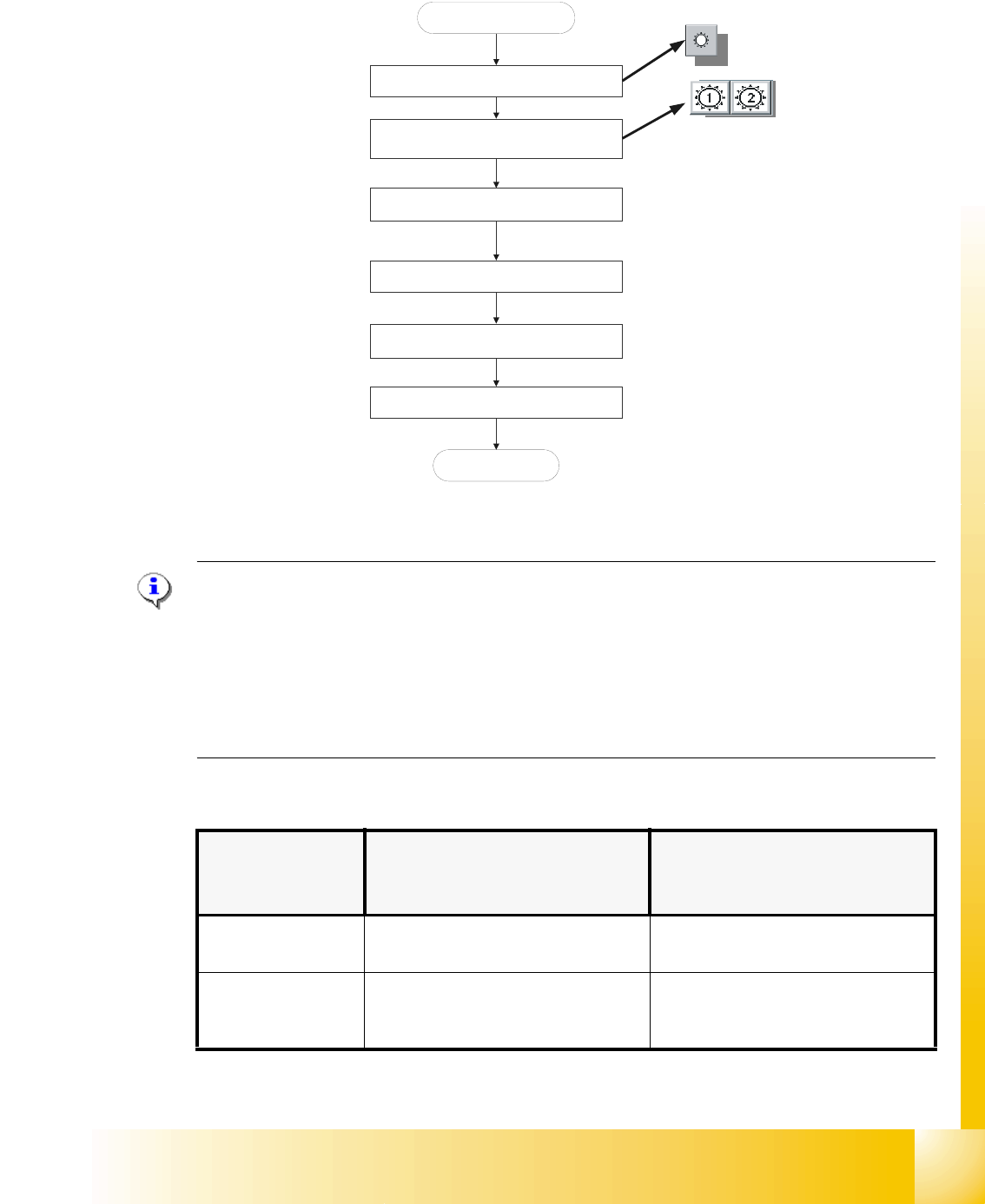
Fig. 6.4 - 15 Flow chart determining air pressure values
Please Note:
Air pressure values, displayed on the screen of the station computer, under option "Measure air
pressure" of the "Single functions", or in the SITEST program, do not correspond to the air
pressure values actually set at the nozzles.
They solely serve to check that the forced air valve is functioning correctly.
Therefore, the air pressure may not be adjusted with the values displayed on the screen.
Instead, use only the values determined with the compressed air testing device. 6
➠ Adjust to the values of the table below:
Air kiss function
circuits
Adjustment with Compressed Air
Testing Device
Measurement taken on Nozzle
Displayed on the Monitor:
(Only in Pick - Up and Placement
Circuit)
pick - up / placement
circuit
150 mbar (100 - 200 mbar) e.g.: 250 mbar
reject circuit
(not used for reject at
HFand X machine) 250 mbar (200 - 300 mbar) reject circuit does not have a sensor
Blast air “ON”
Placement and pick - up circuit
Select appropriate head
Collect & Place Heads
Start SITEST
Use compressed air testing device and
restrictor valve to adjust compressed air
Blast air “OFF”
End
Press the nozzle up, during the
measurement procedure
1 - 68
Student Guide SIPLACE X
6 Collect &Place-Head 6/12 Edition 09/2005
68
Please Note:
The adjustment for the reject circuit is not necessary on the HF/Siplace X machine.
Please Note:
Both forced air circuits are controlled by a single valve and therefore are mutually dependent.
Using two different restrictor valves, it is however possible, to adjust differing pressure values for
each circuit. 6
➠ Repeat these adjustments several times, as the pick - up / placement circuit are mutually
dependent.
Please Note:
Make sure that the test sensor tube is attached air - tight on the nozzle. 6
6.4.11 Other Mechanical Adjustments on the Star
➠ Insert the blast air transition tubes so that they will protrude 0.7 mm from the surface of the
circular arc guide.
Please Note:
The blast air tubes at the valve plungers should be at a distance of 0.2 mm from the encoder
of the DP-axis. 6
1 - 69
Student Guide SIPLACE X
Edition 09/2005 6 Collect &Place-Head 6/12
69
6.5 Nozzle changer
The Siplace HF/Siplace X is supplied with 6 segment or 12 segment collect&place heads. As an
option, a nozzle changer can be installed for each collect&place head. This enables the nozzle
configuration to be changed quickly, thus allowing the Collect&Place head to be quickly adapted
to the needs of the placement process.
6.5.1 Nozzle changer for 12 segment C&P head
The nozzle changer consists of at least one, and up to ten magazines, each with twelve nozzle
garages. The magazines are seated on a common support and each magazine is centered using
two parallel pins and fixed in place with a spring hook.
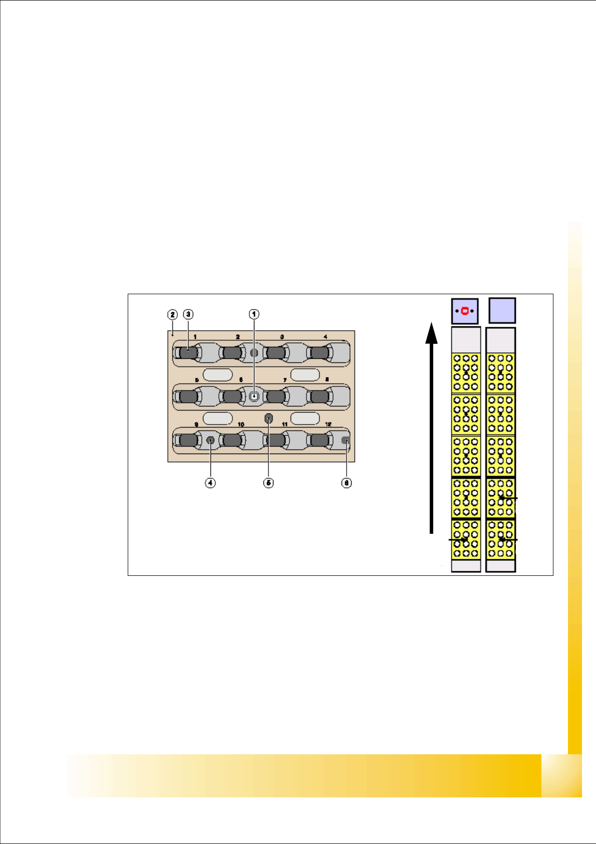
Fig. 6.5 - 1 Nozzle changer and Nozzle Magazin 12 segment C&P head
Legend
(1) Magazine position fiducial (2) Nozzle garage
(3) Locking Plate (4) Hole for the parallel pin for centering the
magazine
(5) Hole for the parallel pin to slide locking
mechanism
(6) Slot for the parallel pin for centering the
magazine
Magazin 6
Magazin 2
Magazin 1
Transport direction