SiplaceX4_en.pdf - 第29页
1 - 5 S tudent Guide SIPLACE X Edition 09/2005 2 Overview 5 The head modularity princi ple developed by Siem ens allows the placement heads to be quickly and easily chan ged. There are four locations fo r at which compon…
1 - 4
Student Guide SIPLACE X
2 Overview Edition 09/2005
4
The heads use two different placement methods:
– the collect&place method, with DLM2 6 or 12 segment C&P heads or the new C&P20 head
with 20 segments, for components from size 0201 (01005 in future) to fine-pitch.
–the pick&place method with the SIPLACE twin head (TH) for fine-pitch and OSC components
The placement machine is based on a torsionally-rigid and vibration-damped cast steel machine
frame. The placement system has two (SiplaceX2), three (SiplaceX3) or four (SiplaceX4) gantries.
These can be quickly and accurately positioned by linear motors, moving independently of one
another in the X and Y directions. Each gantry is equipped with a placement head.
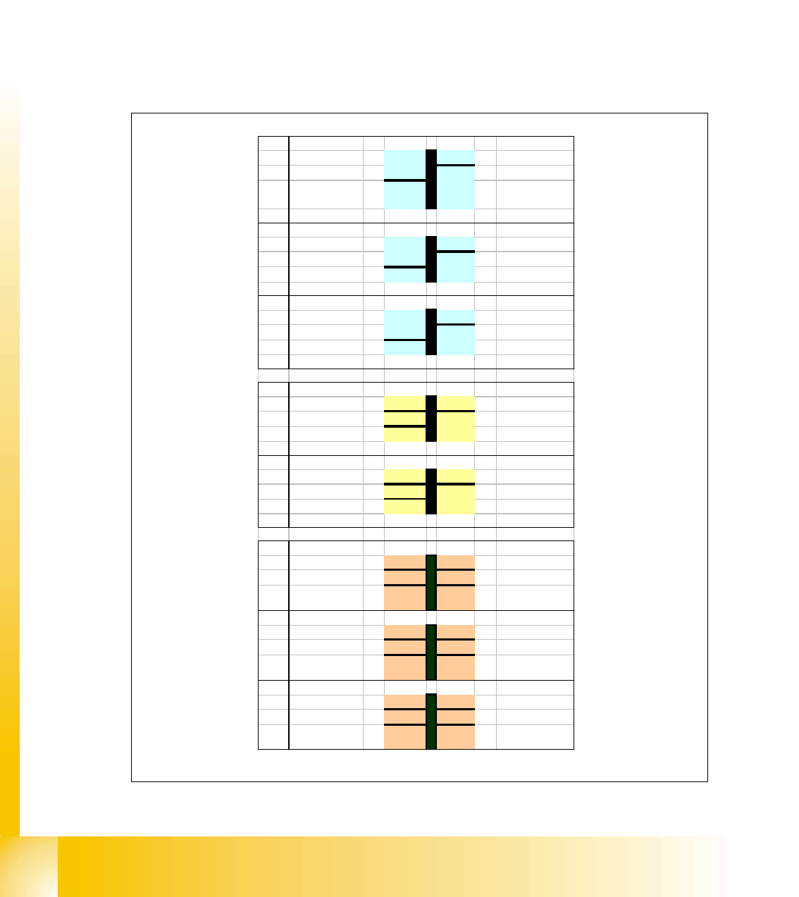
The following placement head configurations are currently possible:
Fig. 2.1 - 2 Possible configurations for Siplace X
PA1 PA2
X2
Gantry3
TH
6 / 12 /C&P20/
TH
Gantry1
X2
Gantry3
6
6 / 12 / C&P20
Gantry1
X2
Gantry3
12
12 / C&P20
Gantry1
X3 6 / 12
Gantry4 Gantry3
TH / 6
6 / 12
Gantry1
X3 C&P 20
Gantry4 Gantry3
TH / 6 / 12
C&P 20
Gantry1
X4 6 / 12
Gantry4 Gantry3
6
6 / 12
Gantry1 Gantry2
6
X4 C&P 20
Gantry4 Gantry3
6 / 12
C&P 20
Gantry1 Gantry2
6 / 12
X4 C&P 20
Gantry4 Gantry3
6 / 12 / C&P20
C&P 20
Gantry1 Gantry2
6 / 12 / C&P20
PA1 Placement Area1 PA2 Placement Area2
1 - 5
Student Guide SIPLACE X
Edition 09/2005 2 Overview
5
The head modularity principle developed by Siemens allows the placement heads to be quickly
and easily changed.
There are four locations for at which components can be fed into the machine.Up to four compo-
nent trolleys or alternatively one or two matrix tray changers can be docked in place of component
tables on the SiplaceX2 machine and one matrix tray changer on the SiplaceX3 machine.
A new generation of feeders with new component tables has been developed for the Siplace X
and the C&P 20 head. A combination of "old" component tables (S-feeders) and "new" component
tables (X-feeders) is possible for a particular placement area, although the C&P20 head will only
use the new feeder generation (X-feeders).The C&P 6/12 and Twin Head can use both compo-
nent table
The placement heads fetch the components from the fixed feeders on the component table or from
the trays in the matrix tray changers and place the stationary PCBs. Each placement head has its
own processing area at Siplace X machines.
– On the single conveyor, there is a placement area for each placement head with one conveyor,
enabling one or two PCBs to be placed simultaneously in the machine.
– On the dual conveyor, there are two placement areas with two conveyors for each placement
head, at which up to four PCBs can be placed simultaneously.
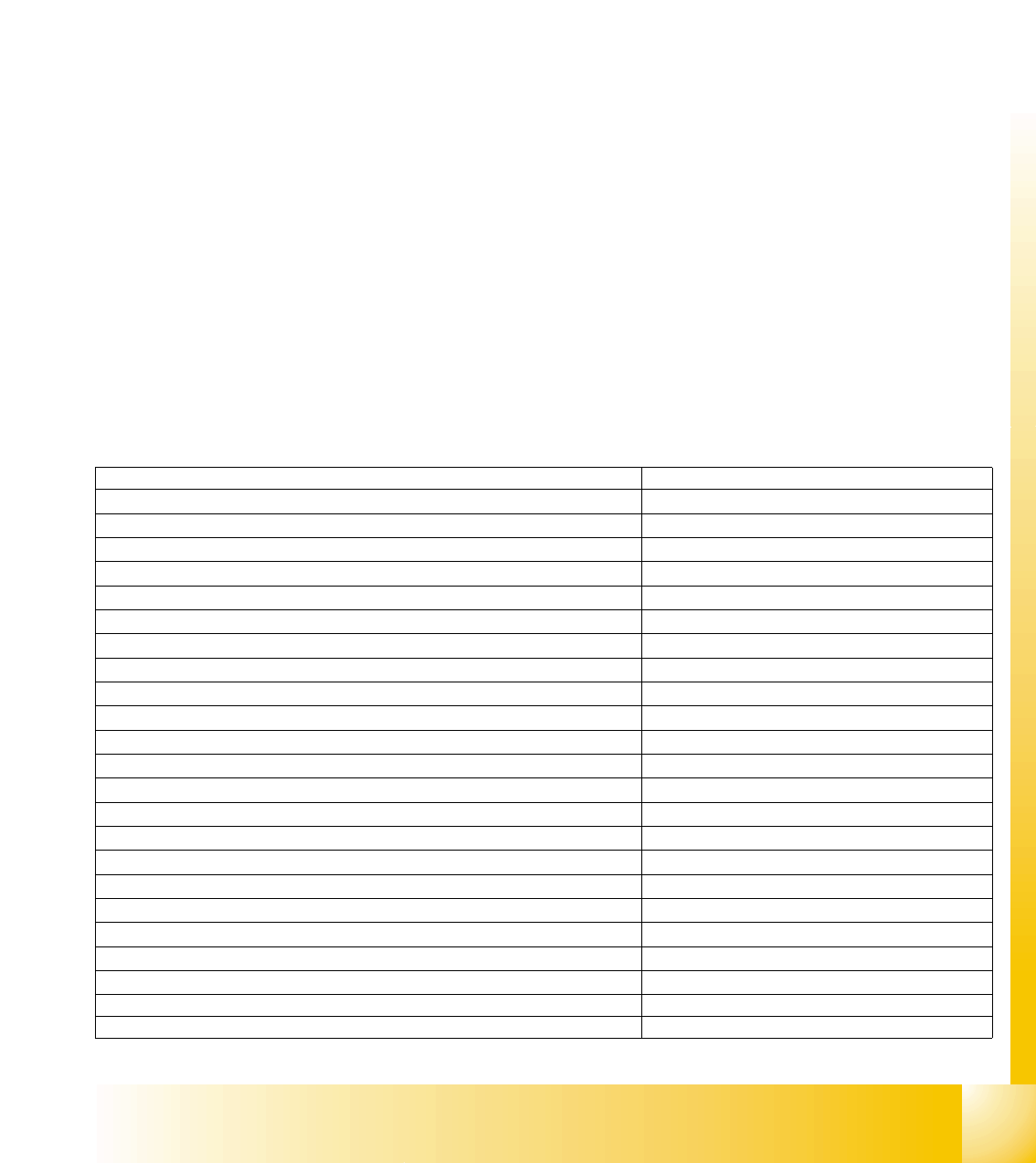
2.1.1 Specification and Configuration of Siplace X
Placement accuracy C&P20 +/- 55 µm , +/-0,7° /(4 sigma)
Placement accuracy C&P12 +/- 60 µm , +/-0,7° /(4 sigma)
Placement accuracy C&P6 +/- 60 µm , +/-0,3° /(4 sigma)
Placement accuracy twin head IC Camera // FC Camera +/-35µm, 0,07°//+/-30µm, 0,07°(4sigma)
Max. component height C&P20 head (LxW) 4.0 mm (6x6mm)
Max. component height C&P12 head (LxW) standard camera 6.0 mm (18,7x18,7mm)
Max. component height C&P6 head (LxW) standard camera 8.5 mm (27x27mm)
Max. component height twin head 25 mm
Nozzle distance twin head 70.8 mm
Max. component size for operation with both nozzles 50 x 50 mm (69 x 10 mm)
Max. component size for operation with single nozzle 85 x 85 mm (125 x 10 mm)
Placement force C&P 20 Head (adjustable) 2,0 +/- 0,5N // 3,5 +/-1N // 4,5+/-1N
Placement force C&P 6 / 12 Head (adjustable) 2,4 - 5 N
Placement force Twin Head (adjustable) 1 - 15 N
Max. component weight standard, twin head 30 g
Max. component weight with restrictions, twin head 100 g
Max. component size stationary IC camera (single shot) 45 x 55 mm
Resolution stationary camera 41 µ / pixels
Minimum ball bump diameter 250 µm
Max. component size stationary flip chip camera (single shot) 16 x 16 mm
Resolution stationary flip chip camera 16 µ / pixels
No. component tables 4
Max. no. MTC2 for X2 2
Max. no. MTC2 for X3 1
1 - 6
Student Guide SIPLACE X
2 Overview Edition 09/2005
6
These data provide basic information for the HF specification. The specification data valid for your
particular machine can be found in your ’Scope of delivery’ document.
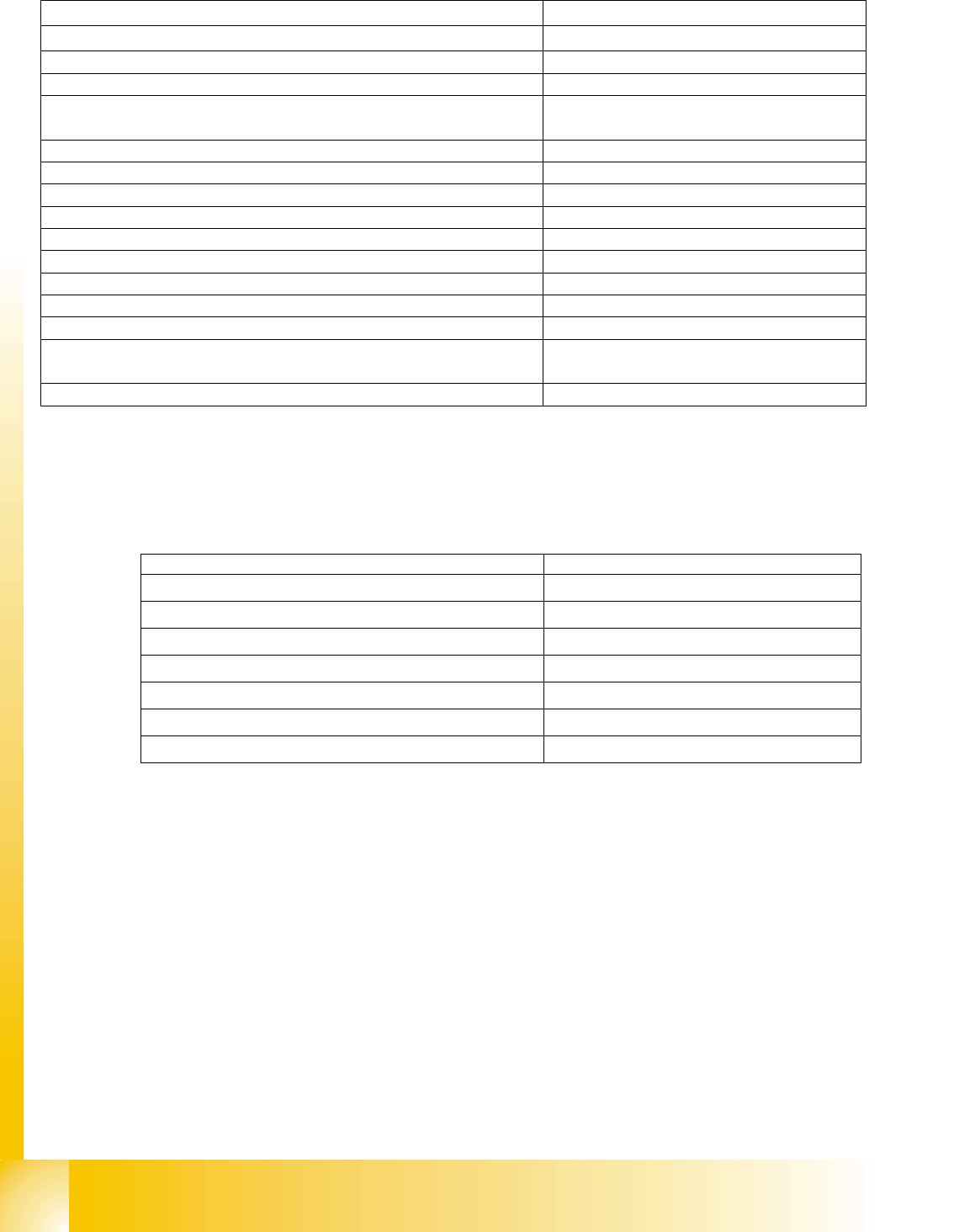
Overview Head Modularity and Benchmark Performance for Selected Configuration Options2
No. tracks 8mm per component table (S-table)
45
No. tracks 8mm X-feeder per X-table
40
PCB widths for single conveyor 50 - 508 mm
Max. PCB lengths for single conveyor (long board option) 50 - 450 mm (610)
Max. PCB widths for dual conveyor
single mode operation
2 x 50-216mm (250 mm)
50-380mm (450mm)
Max. PCB lengths for dual conveyor (long board option) 50 - 450 mm (610)
PCB thickness 0.3 - 4.5mm
Conveyor speed 50 -450 mm/s
Max. PCB weight 3 kg
PCB edge clearance 3 mm
PCB changeover time < 2.5 s
Machine dimensions (L x W) ca. 2380 x 2525mm
Height of PCB transport 830 - 950mm +/- 15mm
Compressed air pressure 5 - 8 bar
Compressed air consumption (C&P12 - twin head or C&P6 - twin
head)
~ 350 NL/min.
Compressed air consumption (C&P20) ~ 200 NL/min.
Placement head combination Placement capacity
PA1 C&P20 - C&P20
40.000 cph
PA1 C&P12 - C&P12
26.800 cph
PA1 C&P6 - C&P6
18.600 cph
PA2 C&P12 - C&P6
20.300 cph
PA2 C&P12
14.000 cph
PA2 C&P6
9.300 cph
PA2 Twin Head
3.700 cph
– cph = components per hour
– PA = Placement area