SiplaceX4_en.pdf - 第286页
1 - 58 S tudent Guide SIPLACE X 6 Collect &Place-He ad 6/12 Edition 09/2005 58 6.4.2 Overview Adjustment s o n the DLM 2 C&P head Description T ools &Equipment Adjustment s Mounting the star onto the motor sh…

1 - 57
Student Guide SIPLACE X
Edition 09/2005 6 Collect &Place-Head 6/12
57
Plug X2, 40-pin 6
Connected to plug X13 on the head board 6
– Voltage supply and track signals for the star-axis drive
– Reference point for the star-axis
– Analog forced air pressure value
– Supply voltages + 5 VDC, ± 15VDC, + 24VDC
Plug X3, 10-pin 6
Connection for the Z-motor and Z-tacho signal (Tacho signal is not use on the HF-machine) 6
Plug X4, 10-pin 6
Connection for the Z-axis track signals 6
Plug X5, 10-pin 6
Connection for the star motor 6
Plug X6, 6-pin 6
Connection for the forced air valve 6
Plug X7, 10-pin 6
Connection for the DP-axis track signals 6
Plug X10, 10-pin 6
Connection for the "Z-axis up" signal 6
Plug X11, 8-pin 6
Connection for the light barrier "Z-axis down" signal (sensor stop signal) 6
Plug X12, 10-pin 6
Connection for the star-axis track signals 6
Plug X13, 10-pin 6
Test connection for the Z-axis track signals
Plug X14, 10-pin 6
not used
Plug X15, 10-pin 6
Test connection for the Star-axis track signals
Plug X15, 10-pin 6
Test connection for the Dp-axis track signals

1 - 58
Student Guide SIPLACE X
6 Collect &Place-Head 6/12 Edition 09/2005
58
6.4.2 Overview Adjustments on the DLM 2 C&P head
Description Tools &Equipment Adjustments
Mounting the star onto the motor shaft
of the star motor
Adjustment with the Po-
wer pack and the gauge
for the star
Check the magnetic neutral
position with the Sitest
(max.Deviation 95 Digit)
Determine zero point correction for the
star
Gauge for zero point cor-
rection / Sitest
Write the determine value in the
Sitest under position
Switch setting on the DLM 2 (Resolu-
tion track signals 10-25) nothing
Switch setting on HF machine
to 25
DP-axis Incremental encoder adjust-
ment to the glass scale (segment) Parallel pin 1,4 - 1,6 mm
Distance 1,5 mm
Adjustment mechanical position of
valve drives
Distance gauge
0,2 mm
0,2 mm Distance plunger to the
valve frame
Light barrier bottom position Z-axis Parallel pin 1,0 mm Distance 1,0 mm
Clamping device on Z-belt
Clamping device have to lay in
the top and bottom position on
the teeth
Belt tension of the Z-axis
Belt tension measure-
ment device
Belt tension
280 +/- 5 Hz
Setting the stop for the Z-axis
Gauge for the Z-mechani-
cal end stop
(03019865-01)
Correct position are necessary to
determine the zero point correc-
tion Z-axis.
Mechanical adjustments Air kiss tubes
on the star
Check with your eyes
Check the distance between
incremental encoder dp and air
kiss tubes.
Adjustments tube for air kiss supply
feeler gauge
Air kiss tubes should be ap-
prox. 0,7 mm over the frame of
the circular guide
Adjustments air pressure values
Compressed air testing de-
vice 150 mbar on open 9x4 nozzle
Table 6.4 - 1 Adjustments on the DLM 2 C&P head
1 - 59
Student Guide SIPLACE X
Edition 09/2005 6 Collect &Place-Head 6/12
59
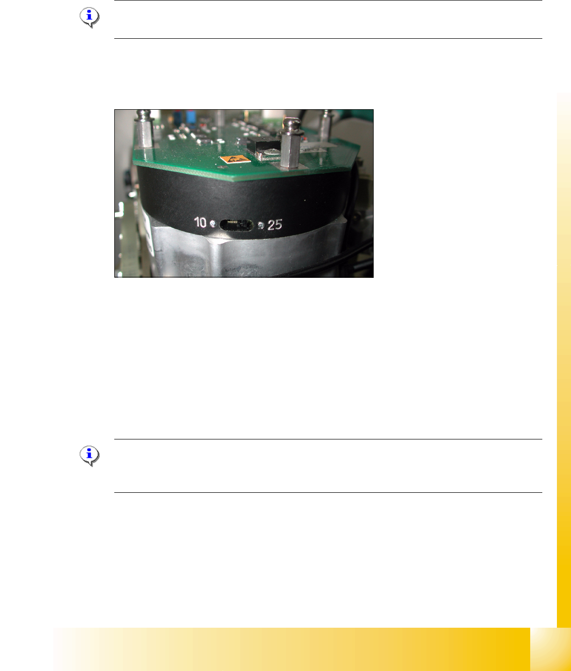
6.4.3 Setting star axis resolution
The switch for the star axis resolution is directly beneath the C&P head on the star motor. 6
Check the setting of this switch (arrow): 6
Please Note:
Only setting the switch, if the machine power is off.
– HS-60 and S-27 HM: Switch position 10
– HF/HF3- and X-machines: Switch position 25
6
Fig. 6.4 - 5 Setting the resolution on the star axis
6.4.4 Setup of the Digital Rotary Transducer of the DP - Axis
➠ Remove sleeve 1 and insert the Star zero point gauge, in order to mechanically fix the Star.
➠ Now, remove sleeve 4 or the sleeve 2 for the 6 segment C&P head as well and align the trans-
ducer.
➠ With the help of a parallel pin, set the rotary transducer of the DP - axis to 1.5 mm, parallel to
the glass pane of the segments.
Please Note:
A parallel pin of 1.4 mm must easily fit through the gap, a parallel pin of 1.6 mm must be too large
to fit.