SiplaceX4_en.pdf - 第119页
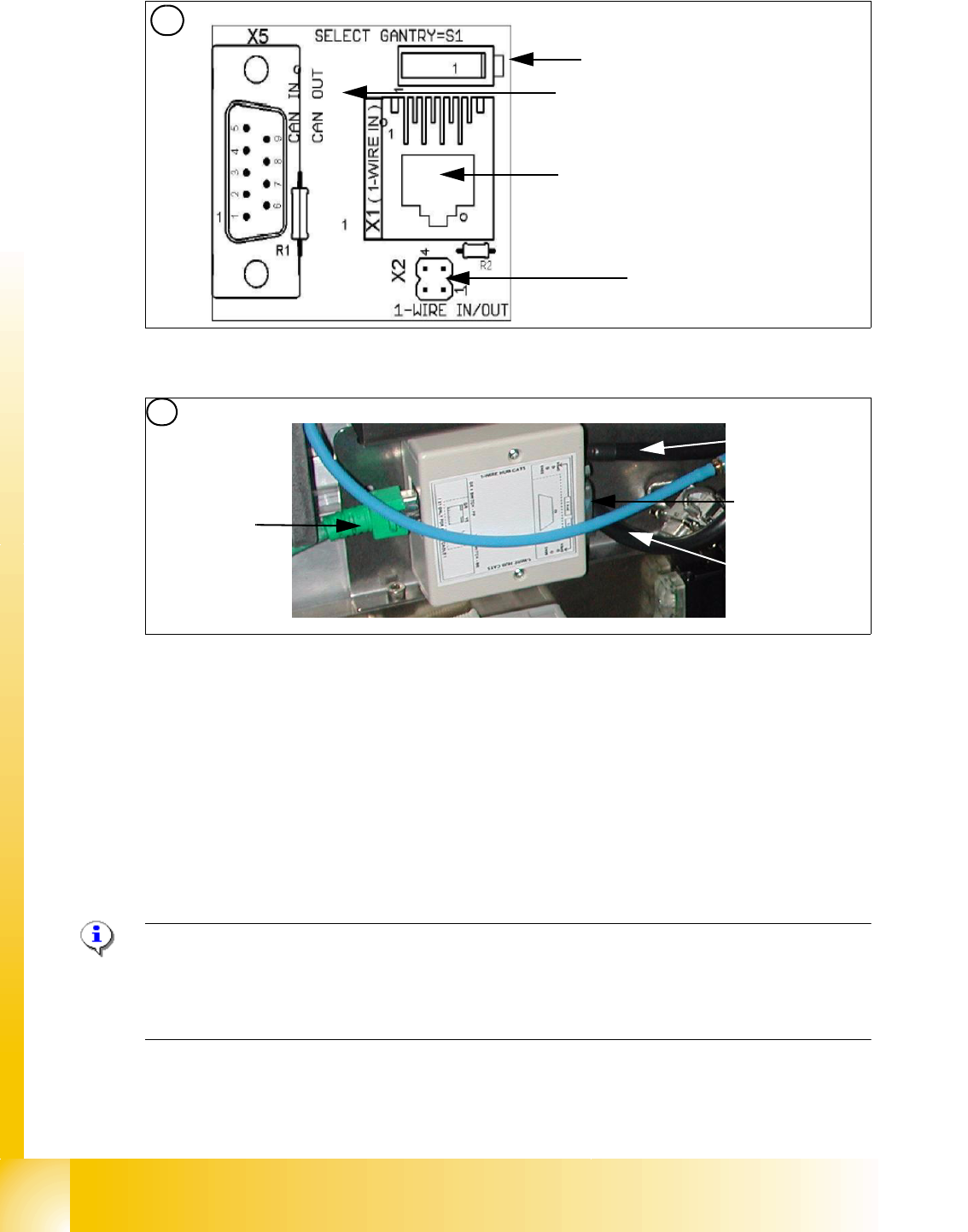
1 - 49 S tudent Guide SIPLACE X Edition 09/2005 3 Communication and Control 49 Fig. 3.5 - 5 1 Wire RS232 interface (03041578-01) Fig. 3.5 - 6 1 Wire CA T 5 Splitter (03040219-01) (1) CA N Bus Interface to I/O module (2) …
1 - 48
Student Guide SIPLACE X
3 Communication and Control Edition 09/2005
48
Function description: 3
When the machine is switched on, each one wire bus is assigned a fixed CAN ID.
One wire in PA1 --> CAN ID: 07d0
One wire in PA2 --> CAN ID:07c0
During initialization of the bus system, each station registers with the master, after which the bus
is ready for operation.
In the non operative mode, the voltage level is 5 V on the one wire bus.
A repeat initialization can be performed with the CACCIA tool (see Function Control and Trouble-
shooting for Service Work).
Pin assignment in machine CAN bus:
Fig. 3.5 - 4 Pin assignment for sub D connectors
One wire bus components 3
Assemblies:
1. 1 wire RS232 bridge on the SUB/MAIN module (to be later integrated into the I/O module)
2. 1 wire CAT 5 Gantry on the trailing interface (board between CAN bus and trailing interface)
3. 1 wire CAT 5 Splitter
4. 1 wire hub for nozzle changer
5. Control board for nozzle changer (integrated into NC, not for DLM heads)
6. 1 set of temperature sensors (replacement only as a set, due to serial number)
7. EEPROM for gantry recognition
120
Ohm
CAN Interrupt95
+24V 1-wire-Bus89
Power Fail74
CAN Reset68
GND53
CAN High47
CAN Low32
GND26
1-wire-Bus 11
AderPin
Pin 1 only for HF machines
1 - 49
Student Guide SIPLACE X
Edition 09/2005 3 Communication and Control
49
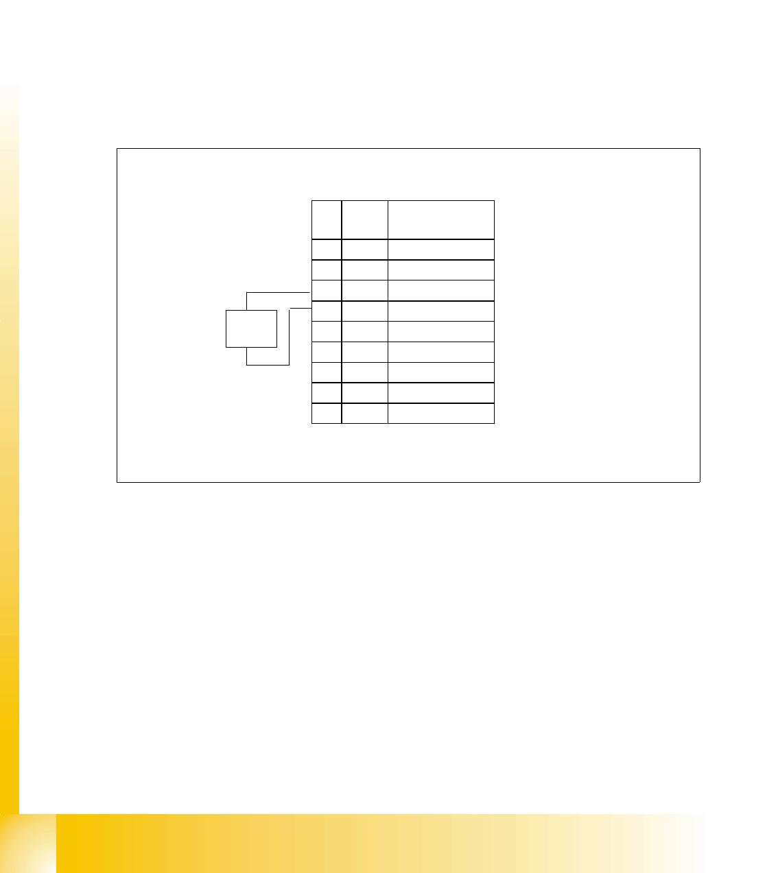
Fig. 3.5 - 5 1 Wire RS232 interface (03041578-01)
Fig. 3.5 - 6 1 Wire CAT 5 Splitter (03040219-01)
(1) CAN Bus Interface to I/O module (2) RS 232 Interface
(3) CAN Bus interface to the machine (4) Switch to recognize the version of the I/O mo-
dule Version 02/03
(5) Switch MA / PC switch to MA (machine) (6) Connector CAT5 cable
LED 1 nozzle changer gantry 1/3 LED 2 Temperatur sensor
LED 3 nozzle changer gantry 4/2 LED 4 Green "OK"
LED 5 Green "Fail"
4
1
2
3
1
5
6
2
Input CAT 5 cable
from RS 232 Interface
Input 24 V for
NC
Output CAT 5
to the NC HUB
Gantry 3or 4
Output CAT 5 to
the 1 Wire gan-
try board
Output CAT 5
to the NC HUB
Gantry 1or 2
1 - 50
Student Guide SIPLACE X
3 Communication and Control Edition 09/2005
50
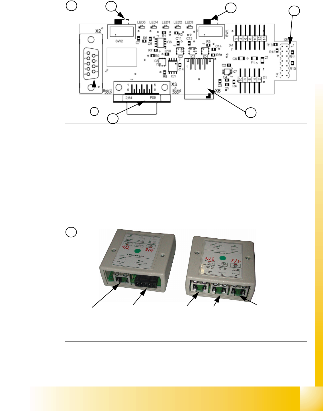
Fig. 3.5 - 7 1 Wire trailing interface board (03042214-01)
Fig. 3.5 - 8 1 wire hub for NC (03041473-02)
Note:
In future we don‘t have the switch for the location code (only HF). The location code for the
nozzlechanger will be realized via hardware, directly in the connector on the location (X112 / X122
/ X132 / X142) at HF and Siplace X. 3
(1) Input CAT 5 cable from the CAT 5
splitter
(2) SUB-D connector for option (query reject con-
tainer)
(3) Connection NC 1 (4) Connection NC 2
on the right side display (2 LED‘s) for NC C&P6/12 Light barrier NC open/closed and Valve NC
open/closed for each row
on the left side two LED‘s directly on the connector
yellow LED: Reject box components connected
green LED: Reject box nozzles connected
3
Switch: position below Gantry 1/2
position above Gantry 3/4
This board is located directly on the CAN
bus connector of the trailing interface.
Connector CAT5 cable from the 1 wire
distributor
Connection to the second Gantry in the
placement area
4
1
2
3
4