SiplaceX4_en.pdf - 第411页
1 - 45 S tudent Guide SIPLACE X Edition 09/2005 8 Collect&Place-Head 20 45 8.4 Adjustment s 8.4.1 Description of the PCB boards on the C&P head 8.4.1.1 Head adapter 20 C&P head Abb. 8.4 - 1 Head adapter for 2…

1 - 44
Student Guide SIPLACE X
8 Collect&Place-Head 20 Edition 09/2005
44
8.3.27 Optical nozzle scanning
(1) After placing the first board the nozzle scanning is activated:
– All nozzles listed in the scan parameters of the machine database will be measured by the
component camera (nozzles such as 1001 - 1014).
– If there is any bright spot with a defined size and brightness the machine displays “nozzle
segment... worn out or polluted”.
(2) Tiny nozzles may touch the solder paste or the glue because of component shift and the min-
imum component height.
3. The number of components per segment (number of head cycles) after which the next nozzle
scanning is executed should be adjusted to customers process needs. This check is always
performed after completing PCB processing.
Description of Air Kiss Control During Placement 8
The air kiss is controlled by the digital pressure control valve, which can be programmed via the
component shape data in the SIPLACE PRO programming computer.
1 - 45
Student Guide SIPLACE X
Edition 09/2005 8 Collect&Place-Head 20
45
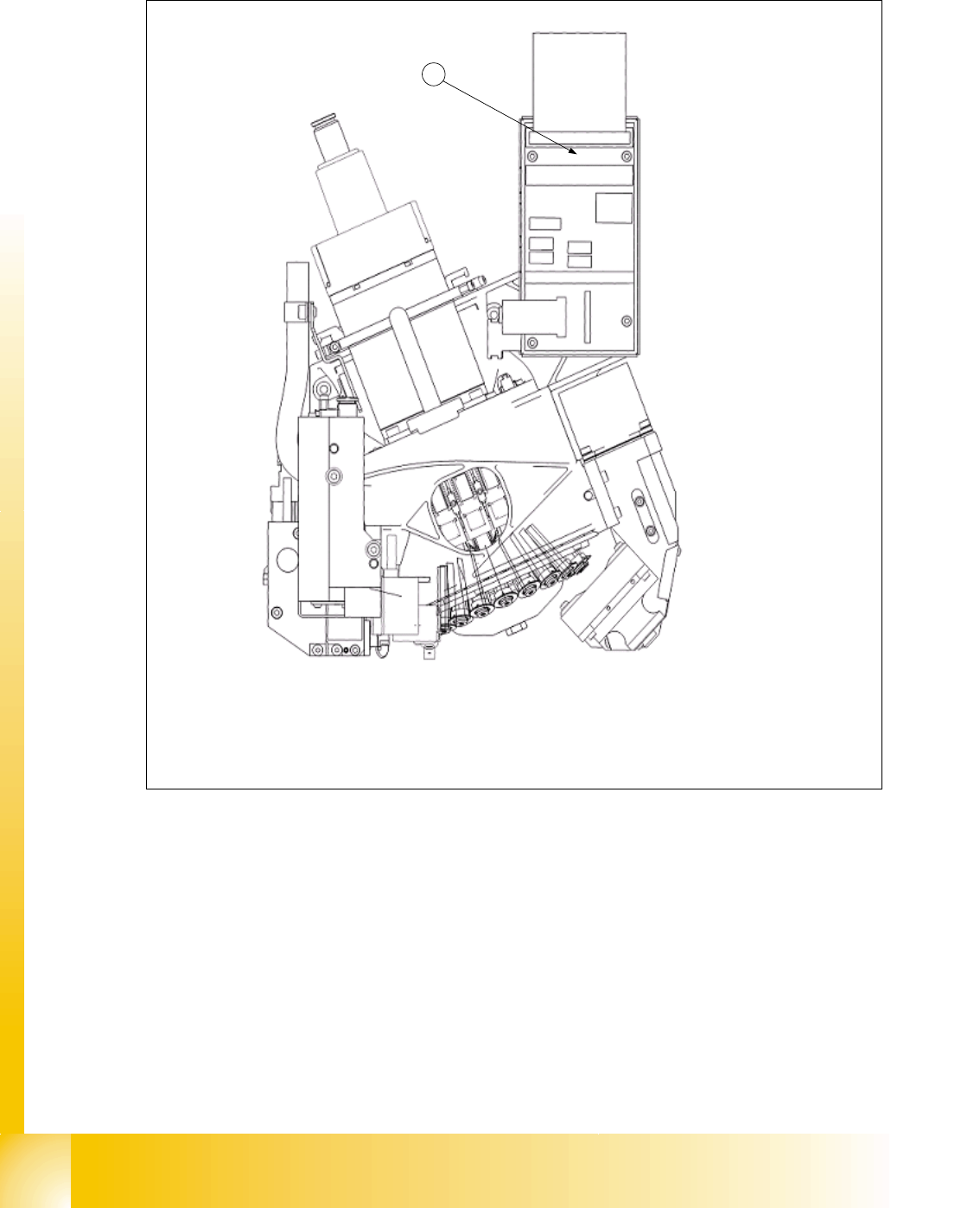
8.4 Adjustments
8.4.1 Description of the PCB boards on the C&P head
8.4.1.1 Head adapter 20 C&P head
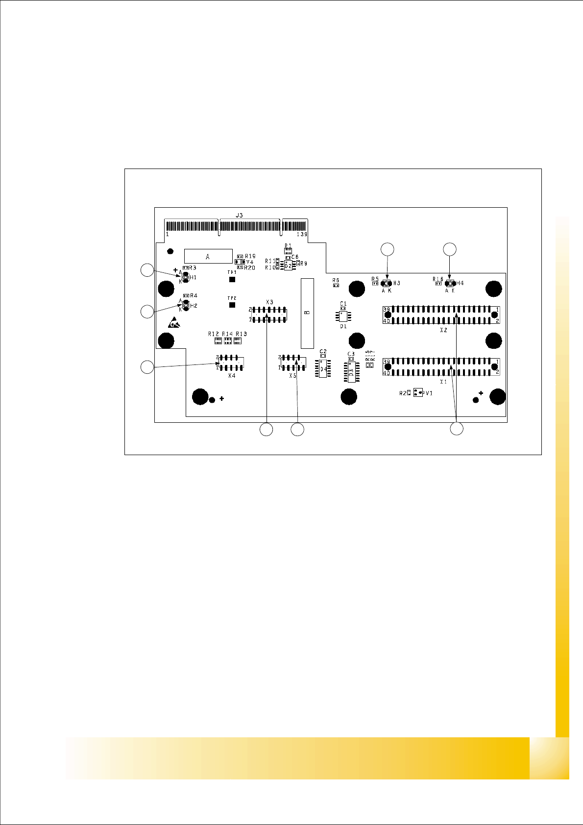
Abb. 8.4 - 1 Head adapter for 20 C&P placement head
Legend:
(1) X1, X2 connection to intermediate distributor board
(2) X5 Track signals of the Z-axis
(3) X3 Test connector : Seriell Parallel Interface (SPI)- Bus
(4) X4 Track signals of the Star axis
(5) H2 LED (green) to indicate 24V of DP- drives
(6) H1 LED (red) to indicate 24V at C&P20 head
(7) H3 LED (green) to indicate component Sensor
(8) H4 LED (red) to indicate Hardware- error C&P20 head
1
23
4
5
6
7 8