SiplaceX4_en.pdf - 第265页
1 - 37 S tudent Guide SIPLACE X Edition 09/2005 6 Coll ect &Place-Head 6/12 37 6.3.20 PCB placement finished – A ll components are pla ced at the corrected pl acement positions at th e PCB board positions. – A fter p…
1 - 36
Student Guide SIPLACE X
6 Collect &Place-Head 6/12 Edition 09/2005
36
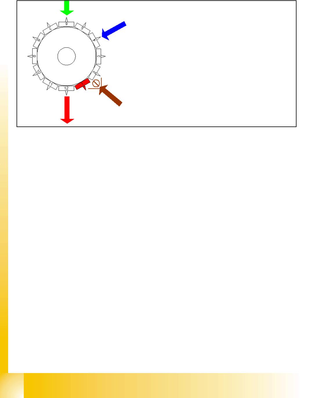
6.3.17 Placing 12th Component
Fig. 6.3 - 17 Placing 12th component
6.3.18 Pick up and placement cycle for the next components...
– After all the components of the first head cycle are placed onto the board, the gantry axes move
the placement head to the pick up position of the next pick up cycle.
– The next pick up cycle for components 13 to 24 (7 to 12 for 6 nozzle head) is executed.
– And so on and so on..... If necessary the machine executes repair cycles.
6.3.19 Segment with a „defective component“
If the optical centering of a component fails (Ident.error) or the vacuum check before placement
fails (Vacuum error) alternatively comp.check / height measurement at the comp. sensor fails the
component is not placed and remain on the nozzle;
– the turning station turn now this nozzle to the pick up angle of the new component when this
segment is in turning position.
If this segment is in pick up position:
– the reject procedure is activated
– X-/Y-axes move from feeder pos. to their reject position
– the component is rejected by an air kiss to comp. reject box
– X-/Y-Axes return to feeder position
– the new component is picked
This rejected component is placed after all placement cycles by a „repair cycle“.
Star position 330°
– Vision system: optically centering of the 6th
component on the other gantry
– DP-station: turn 4th nozzle to the pick up angle
for the next pick up cycle.
– pick up / placement station: place 12th compo-
nent
– synchronization: after placing the 12th compo-
nent of this gantry placement enable signal is re-
turned to MC.
– component sensor: during the next Star step the
nozzle length at segment 2 is measured.
1 - 37
Student Guide SIPLACE X
Edition 09/2005 6 Collect &Place-Head 6/12
37
6.3.20 PCB placement finished
– All components are placed at the corrected placement positions at the PCB board positions.
– After placing the last component the gantry axes move to the waiting position.
– The machine activates the transport system and moves the board to the output conveyor.
– Finally the machine sends the number of consumed components (placed and rejected ones)
to the line computer.
– The OIS (Operator Information System) calculates the placement statistics referring to the pro-
grammed station setup, the programmed cluster or the last reset time. This meaningful place-
ment statistics help to optimize the production process.
– The machine is ready for the next board.
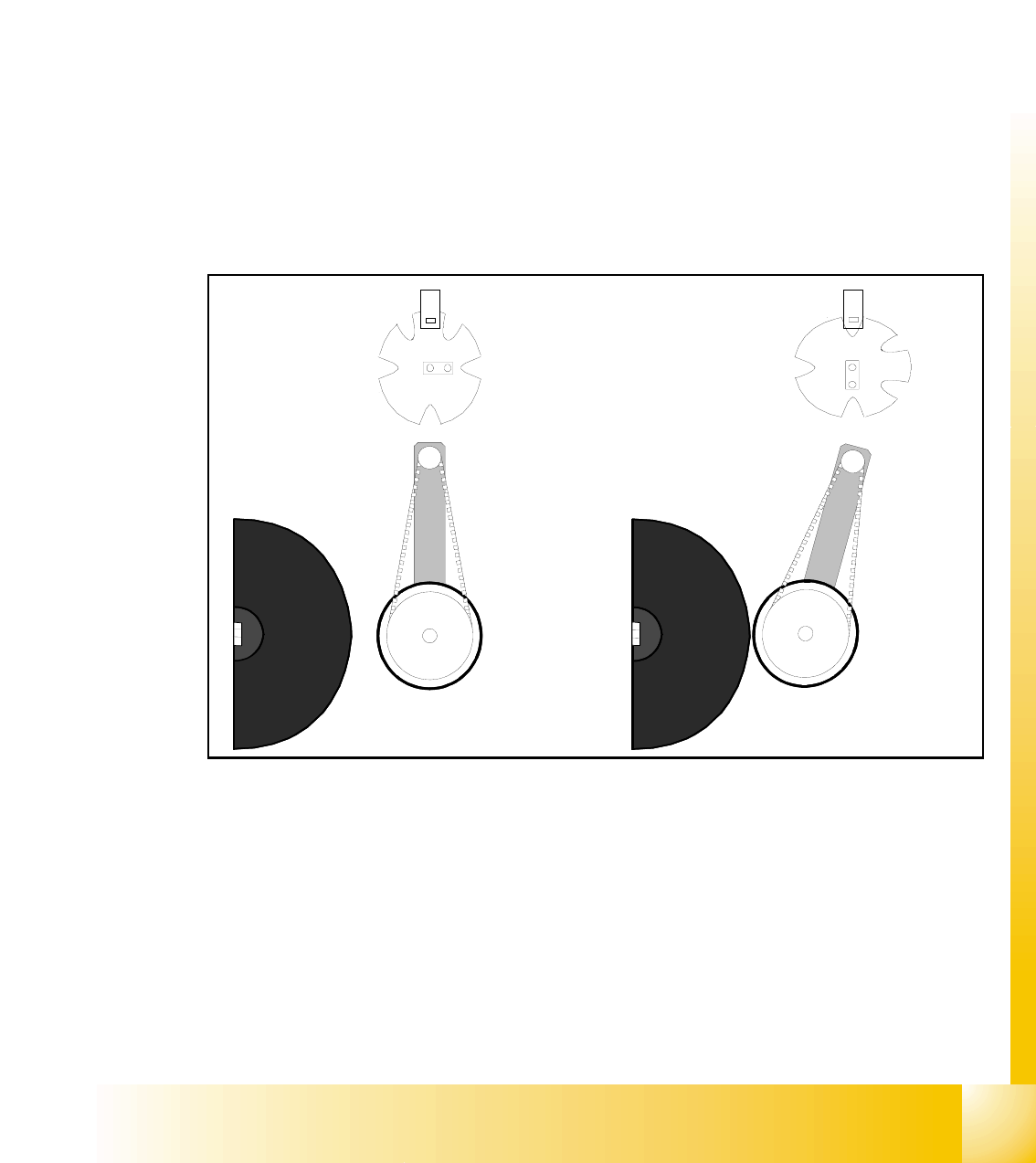
6.3.21 Detailed turning process at DP-station - 1. Swiveling in
Fig. 6.3 - 18 Detailed turning process at DP-station 1. Swiveling in
– Picture 1 shows the initial position.
– From initial position the stepper-motor turns 90° to swivels in.
– The DP-station swivels in and contacts the sleeve (incremental scale).
– The stepper motor is controlled by the light barrier at the cam disc.
– Picture 2 shows the state when swiveled in.
– This is the start requirement for the drive of the DP-axis.
1.
2.
1 - 38
Student Guide SIPLACE X
6 Collect &Place-Head 6/12 Edition 09/2005
38
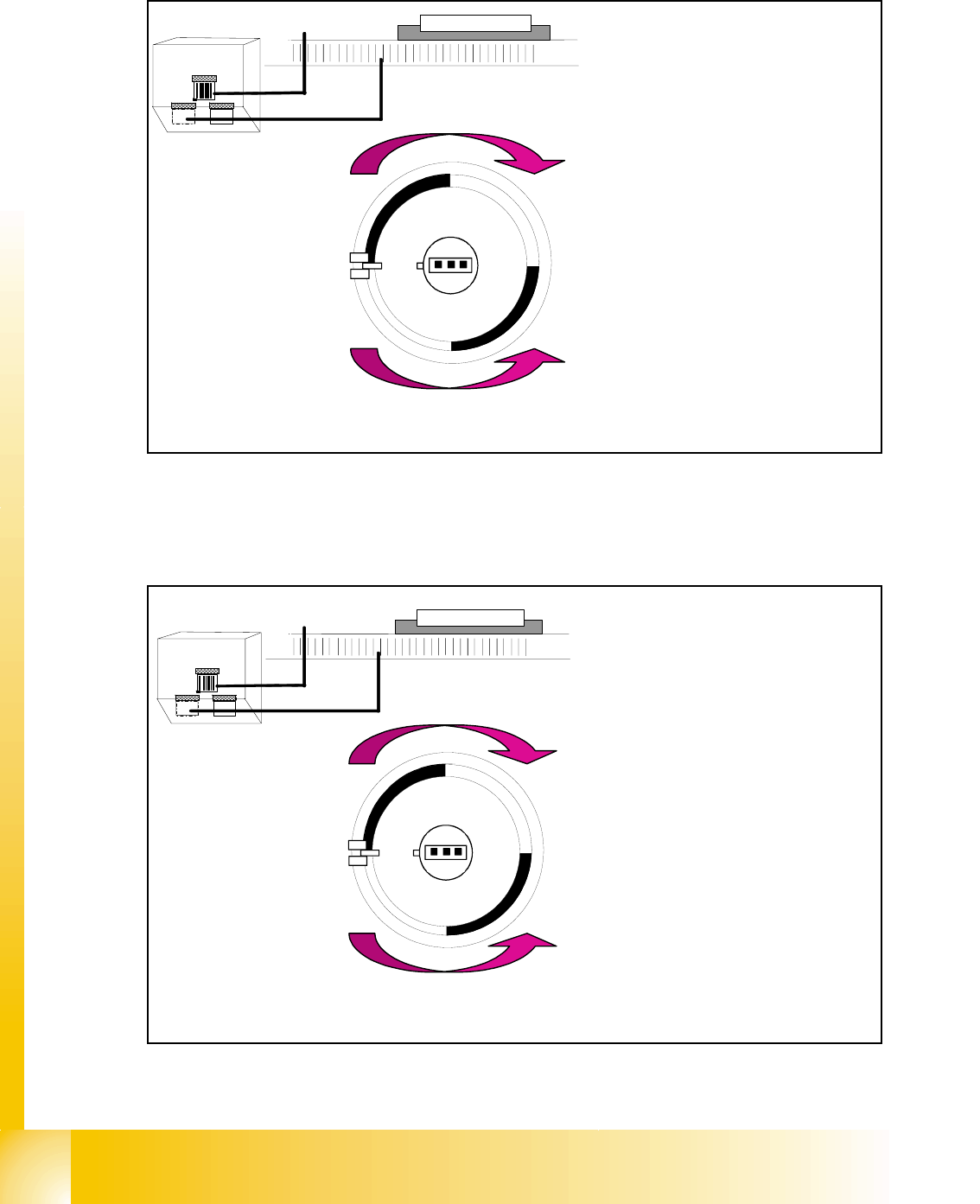
6.3.22 Detailed turning process at DP-station - Positioning to pick up angle
Fig. 6.3 - 19 Detailed turning process at DP-station - Positioning to pick up angle
6.3.23 Detailed turning process at DP-station - Positioning to placement angle
Fig. 6.3 - 20 Detailed turning process at DP-station - Positioning to placement angle
Zero pulse
window
Track signals
bright dark
transition is
zero pulse
¼ turning
Turning directions
– The axis drive moves the seg-
ment to the 0-pulse and checks
the signal level for 3 digits.
– The axis runs in absolute posi-
tioning mode to one of the zero
pulses and check this zero
pulse. For a pick up angle of
90° the axis drive move direct
to the 90° black-bright transi-
tion.
– End signal is set when actual
position deviation is within al-
lowed deviation of position.
– There is no difference between
0° and 180° / 90° or -90° pick
up angle.
Zero pulse
window
Track signals
bright dark
transition is
zero pulse
¼ turning
Turning directions
– When DP-station is swiveled in
the axiscontroller is activated
and ..
– .. the actual position is set to zero
by setting the position counter
DP-axis to 0.
– The DP-drive is operated in rela-
tive positioning mode.
– The DP-axis starts to the target
position taken from calibrated,
programmed and centered val-
ues.
– End signal is set when actual po-
sition deviation is within allowed
deviation of position.