SiplaceX4_en.pdf - 第152页
1 - 6 S tudent Guide SIPLACE X 4 Services to the machine Edition 09/2005 6 4.2.2 Main distribut ion Unit, section 2 Fig. 4.2 - 2 section 2, main distributor Legend: 1. T erminal block X1qa (GND, +3.3V , +5V , +15V , -15V…

1 - 5
Student Guide SIPLACE X
Edition 09/2005 4 Services to the machine
5
4.2.1 Naming Convention of Connectors and Cables
The wiring on the Siplace X is highly structured. Every cable, connector, distributor uses an exact
term, which is dedicated to the sections and units in question.The name convention and the
systemacy is explained at the original Siplace X type; this is basically valid for all the Siplace X
machines:
Section 2: term q+ 4
– Main-distributor section 2: term X1qa, X2qa, X3qa, ...
– CAN I/O module (A1): term X1
qb, X2qb, X3qb, ...
– Vision DC/DC converter (A3): term X1
qc, X2qc, X3qc, ...
– Vision control unit (A4): term X1
qd, X2qd, X3qd, ...
– Circuit board 8-fold AND operation (A5): term X1
qe, X2qe and X3qe
Section 4: term r+ 4
– Sub-distributor section 4: term X1ra, X2ra, X3ra, ...
– CAN I/O module (A1): term X1
rb, X2rb, X3rb, ...
– Vision DC/DC converter (A3): term X1
rc, X2rc, X3rc, ...
– Vision control unit (A4): term X1
rc, X2rd, X3rd, ...
– Circuit board 8-fold AND operation (A5): term X1
re, X2re and X3re
– Handing over constituent (A2): term X30
ra and X31ra
Placement head gantry 1: term a+ 4
– Gantry distributor: 00 353593 aa
– Gantry interface: 00 363330
ab
– Head interface: 03000900
ac
– Vision board: 03 321469
au
Placement head gantry 3: term b+(up to Machine MA.No. xx / from MA .No. xx is the term c+) 4
– Gantry distributor: 00 353593 ba
– Gantry interface: 00 363330
bb
– Head interface: 03000900
bc
– Vision board: 03 321469
bu
Placement head gantry 4: term d+ 4
– Gantry distributor: 00 353593 da ; Head interface: 03000900 dc
– Gantry interface: 00 363330
db ; Vision board: 03 321469 du ; Computer unit: X1p+
1 - 6
Student Guide SIPLACE X
4 Services to the machine Edition 09/2005
6
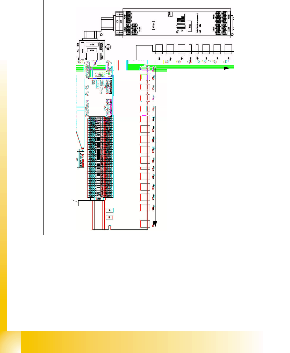
4.2.2 Main distribution Unit, section 2
Fig. 4.2 - 2 section 2, main distributor
Legend:
1. Terminal block X1qa (GND, +3.3V, +5V, +15V, -15V, +24V, +52V, various signals)
2. DC/DC converter for Twin head stationary cameras and PCB camera placement area 2 (A3)
3. Vision illumination control board for Twin head stationary cameras (A4)
4. CAN bus I/O module (SLIO) (A1)
5. Connector bar (connector X2qa - X6qa, X71qa - X74qa and X9qa - X24qa)
6. 8-fold AND operation for safety loop (A5)
52
3
1
4
6
1 - 7
Student Guide SIPLACE X
Edition 09/2005 4 Services to the machine
7
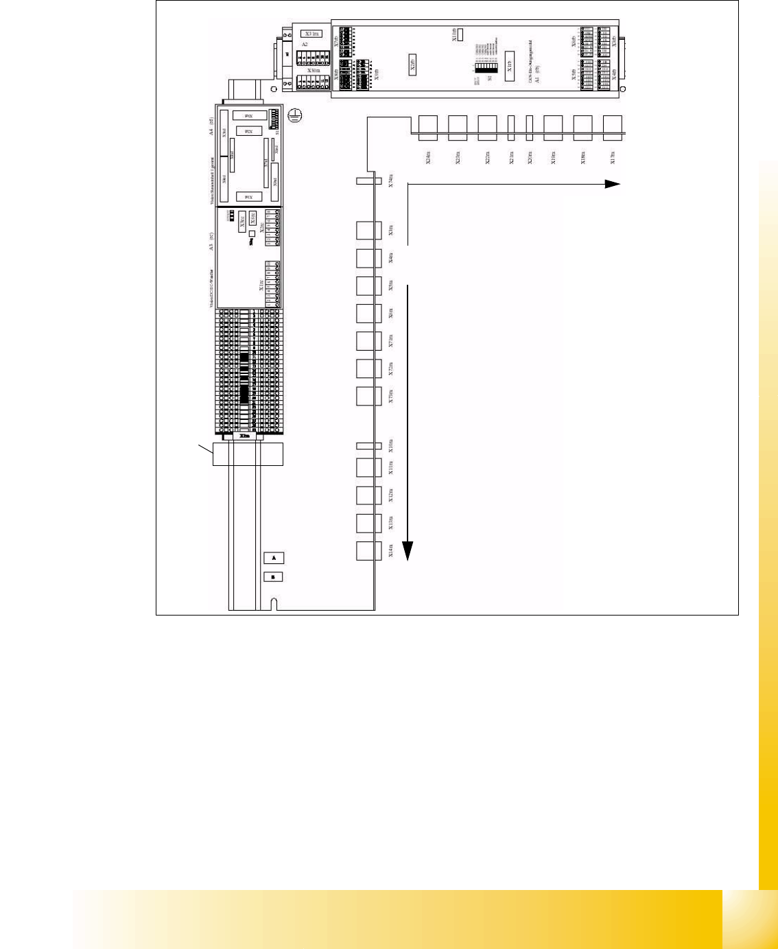
4.2.3 Sub distribution Unit, section 4
Fig. 4.2 - 3 section 4, sub distributor
Legend:
1. Terminal block X1ra ((GND,+5V,+15V,-15V,+24V,+52V, various signals)
2. DC/DC distributor for PCB camera (for stationary cameras future application) on placement
area 1
3. Vision illumination control board for stationary cameras placement area 1 (future application).
4. CAN I/O module (SLIO)
5. Connector bar (connector X3ra - X6ra, X71ra-X74ra, X10ra - X24ra)
6. 8-fold AND operation for safety loop (A5)
52
3
1
4
6