SiplaceX4_en.pdf - 第168页
1 - 22 S tudent Guide SIPLACE X 4 Services to the machine Edition 09/2005 22 Stop Button Loo p 4 The stop button loop consists of 6 contac ts which are s witched in parallel mode . If 1 ore mo re stop button is pr essed,…
1 - 21
Student Guide SIPLACE X
Edition 09/2005 4 Services to the machine
21
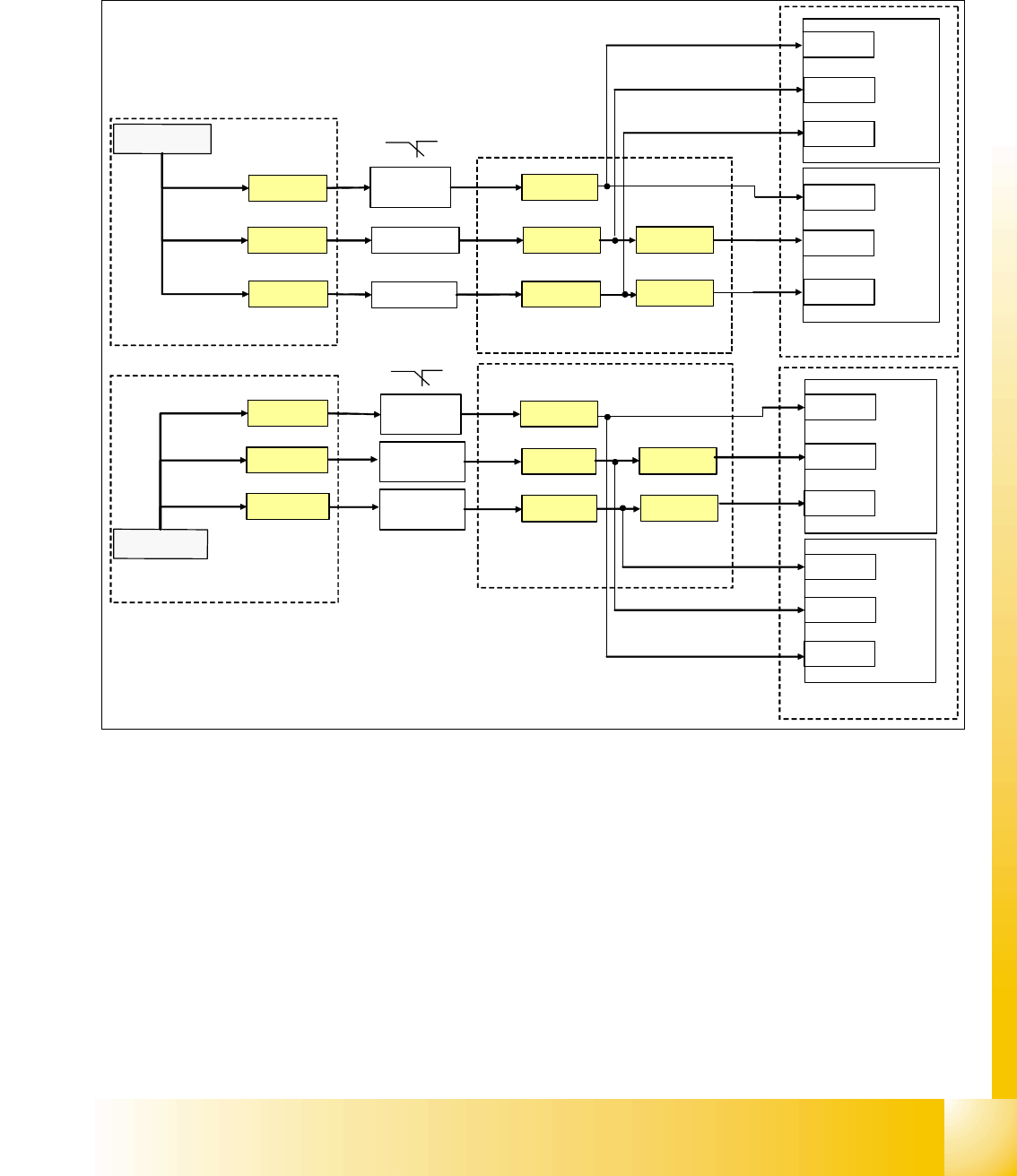
Cover control Loop 4
The cover control loop consists of 6 contacts (4 cover and 2 transport) and they are switched in
parallel mode. If 1 ore more cover is open, the contact is closed and the 24 V signal sets an input
on CAN I/O module in section 4 and shows, that any cover is open.
.
Fig. 4.2 - 15 cover control loop
24V
Cover 3
X14qa_1
X
1
q
a
_
2
4
V
24V
Cover 2X13qa_1
24V
X13qa_4
X14qa_4
PCB-
output
X11qa_1
X11qa_4
24V
Cover
4
X14ra_1
X
1
r
a
_
2
4
V
24V
Cover
1
X13ra_1
24V
X13ra_4
X14ra_4
PCB-
output
X11ra_1
X11ra_4
CAN I/O - module
section
CAN I/O - module
Section 4
8-fold
AND
8-fold
AND
X1qe_4
X1qe_2
X1qe_6
X5qb_4
X5qb_2
X19qa_4
X24qa_4
X24ra_4
X19ra_4
X5qb_6
X5rb_4
X5rb_6
X5rb_2
X1re_4
X1re_2
X1re_6
main distributer, section 2
sub distributer, section 4
main distributer, section 2
sub distributer, section 4
main , section 2
sub, section 4
1 - 22
Student Guide SIPLACE X
4 Services to the machine Edition 09/2005
22
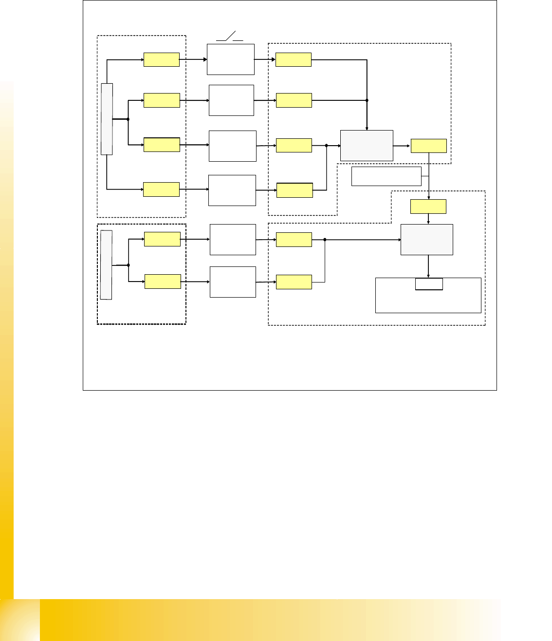
Stop Button Loop 4
The stop button loop consists of 6 contacts which are switched in parallel mode.
If 1 ore more stop button is pressed, the contact is closed and the 24 V signal sets an input on
CAN I/O module in section 4 and shows, that any stop button is pressed.
Fig. 4.2 - 16 stop button loop
24V
stop button
PCB- output
right
stop button
PCB- output
left
X1qa_stopbutton
stop button
PCB- input
right
X11qa_1
X12qa_1
X11ra_1
X
1
q
a
_
2
4
V
24V
24V
X73qa_2
X73ra_2
stop button
right
(pneumatic)
X10qa_1
24V
stop button
PCB- input
left
X12ra_1
X
1
r
a
_
2
4
V
X10qa_3
X11qa_6
X12qa_6
X11ra_6
X12ra_6
stop button
left
(power supply)
X9qa_1 X9qa_3
X1ra_stopbutton
C
A
N
I
/
O
-
m
o
d
u
l
e
s
u
b
d
i
s
t
r
i
b
u
t
e
r
,
s
e
c
t
i
o
n
4
3
4
Eingang
cable term : 03002521
X4rb_2
sub distributer, section 4
main distributer, section 2
main distributer, section 2
sub distributer, section 4
1 - 23
Student Guide SIPLACE X
Edition 09/2005 4 Services to the machine
23
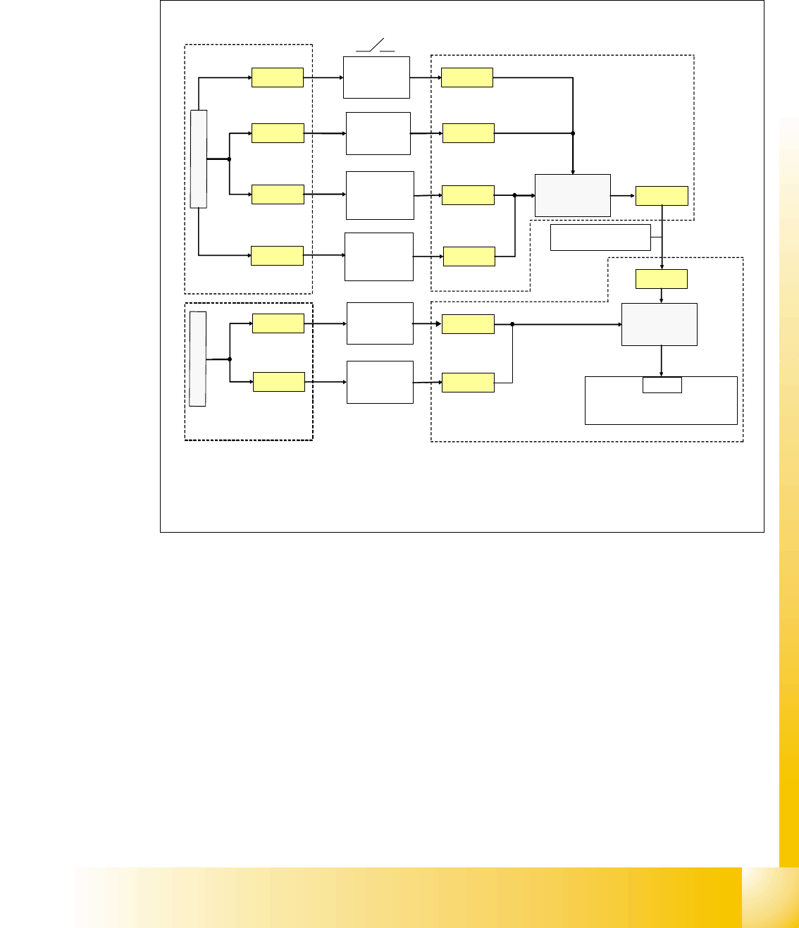
Start Button Loop 4
The start button loop consists of 6 contacts and they are switched in parallel mode.
If 1 ore more start button is pressed, the contact is closed and the 24 V signal sets an input on
CAN I/O module in section 4 and shows, that any start button is pressed.
Fig. 4.2 - 17 start button loop
24V
stop button
PCB- output
right
stop button
PCB- output
left
X1qa_startbutton
start button
PCB- input
right
X11qa_1
X12qa_1
X11ra_1
X
1
q
a
_
2
4
V
24V
24V
X73qa_1
X73ra_1
start button
right
(pneumatic)
X10qa_1
24V
X12ra_1
X
1
r
a
_
2
4
V
X10qa_2
X11qa_5
X12qa_5
X11ra_5
X12ra_5
start button
left
(power supply)
X9qa_1 X9qa_2
X1ra_startbutton
C
A
N
I
/
O
-
m
o
d
u
l
e
s
u
b
d
i
s
t
r
i
b
u
t
e
r
,
s
e
c
t
i
o
n
4
3
4
Eingang
cable term: 03002521
X4rb_1
sub distributer, section 4
main distributer, section 2
sub distributer, section 4
main distributer, section 2
start button
PCB- input
left