SiplaceX4_en.pdf - 第535页
1 - 30 S tudent Guide SIPLACE X 1 1 Sitest Edition 09/2005 30 1 1.2.14 Calibrate and teach machine positions New function for calibrate the positions is the teach menu before calibrate, so that you can teach the correct …

1 - 29
Student Guide SIPLACE X
Edition 09/2005 11 Sitest
29
Saved are all this data and coordinates in: KAM_DAT.MA in Data bloc camera 11: (for gantry 2)
Kamera_Position_X / 1483500, Kamera_Position_Y/ 1370500, Kamera_Offset_Z/ 5000
Calibration data of IC camera saved in mapp_pkt.ma file.
– Calibration IC camera position fiducial
FC camera: (Option) 11
– After measuring the head height of TWIN head the TWIN -FC camera is calibrated.
– The first measurement is the focus level. That means, the twin head move with the Z-axis of
the cover from the stationary camera. (This height is the centering height for bottom side of
components.)
– The Pixel size in µm of the camera is determined next. Saved as:/XU_Pixel / YU_Pixel/ of cam-
era 15(in 19600 nm).
– The camera center of the TWIN- FC-camera refer to the zero point of the machine (X- / Y-
counter zero position).
Saved are all this data and coordinates in: KAM_DAT.MA in Data bloc camera 15: (for gantry 2)
Kamera_Position_X / Kamera_Position_Y/ Kamera_Offset_Z/
– Calibration IC camera position fiducial
Twin head segment offset bottom at segment 1 and 2: 11
– The segment offset determined the middle of the segment to the PCB camera. That means the
D axis, center of sleeve of the TWIN (IC) -placement head refer to the camera center of PCB-
camera. This measurement is only done in the lower position so the result is saved as an
offset "2" at the head.
The coordinates saved in PIP_OFF.MA at Data bloc /Pipetten-Offsets unten Kopf 2/ Pipetten-Off-
sets unten Segment 1(2) Offset_X /Offset_Y /
Nozzle changer (C&P head, Twin head): 11
Note: Precondition for calibrate the nozzle changer is to check or determine the zero point cor-
rection for the D - Axis Twinhead, the configuration of the nozzle changer and the fill level.
– Each nozzle magazine has an fiducial which will recognize during the calibration procedure at
first.
– After that, the machine recognize the two fiducial of the holder from the magazine on the left
and right side.
– optional, calibrate the pick up height from the nozzle changer.
– optional, calibrate the reject position from the nozzle changer, necessary to reject nozzle which
are defekt.
Calibrate closed vacuum: 11
This function measure onto the fixed conveyor rail with the nozzle 518 the closed vacuum values
of the vacuum system for the segment 1 and 2.

1 - 30
Student Guide SIPLACE X
11 Sitest Edition 09/2005
30
11.2.14 Calibrate and teach machine positions
New function for calibrate the positions is the teach menu before calibrate, so that you can teach
the correct position for a successfull calibration.
11.2.14.1 Conveyor edges (Conveyor rails)
This new calibration procedure is necessary for the modular conveyor system.
With the modular conveyor are all conveyor rails adjustable. For adjustment the conveyor rails we
use one stepper motor which is connected via a toothed belt to the driver unit. The position of the
rails are recognize with a BERO and therefore we have different switch point on each conveyor
rails. With this calibration the switch points are optimized of the entire travel range of the width
adjustment. The calibration is necessary that all three Driver units move the conveyor rails paral-
lel.
Automatically Sequence (Transport mapping):
– Initialize the driver unit, move to the right side (limit switch)
– Driver unit recognize the fixed conveyor rail (rails dual conveyor) move the conveyor rails a
standard position of 55mm.
– The driver unit move the moveable conveyor rail step by step (10mm steps) and determined
the offset of the rail positions for the three drivers.
– This calibration of the rail position will be done for width adjustment wider and smaller.
– The results are saved in the conveyor controller as correction values and taken into account
later when setting and measuring the conveyor width.
Note:
The calibration must be done for conveyer 1 and 2.
11.2.14.2 Conveyor width calibration
The conveyor width calibration determine the width with a 100mm wide standard PCB board.
11.2.14.3 PCB reference corner
– Select gantry 1 or 2.
– Select PCB reference corner position right or PCB reference corner position left (dual con-
veyor)
– Moves the active gantry with the PCB camera over the reference corner position and switches
the screen display to the PCB camera for checking purposes.
The reference corner position is visible in the camera's field of view. Teaching mean now the
camera center is to align with the right corner of the PCB.
1 - 31
Student Guide SIPLACE X
Edition 09/2005 11 Sitest
31
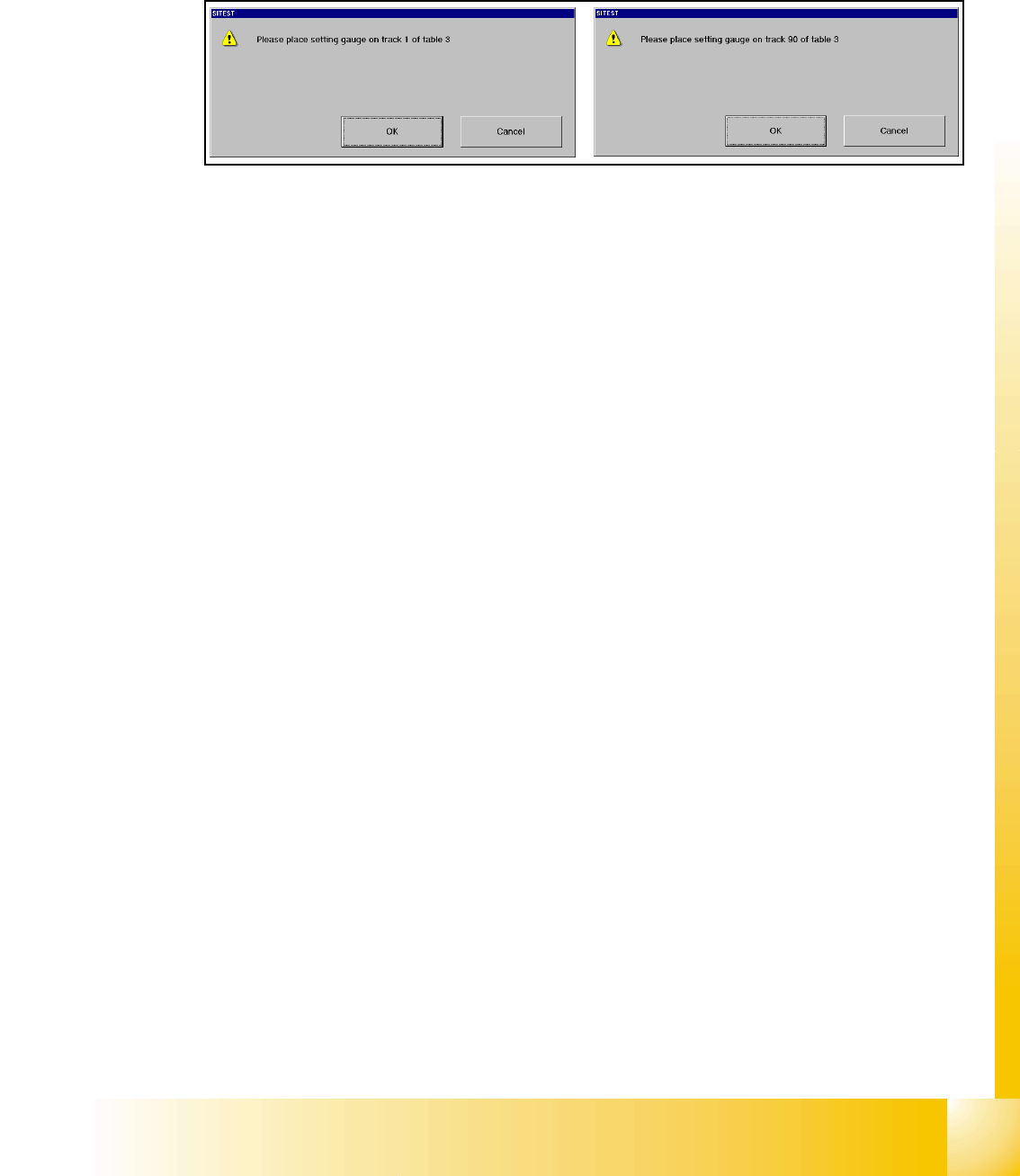
11.2.14.4 Pick up position (Calibrate the component table Track 1- 90)
Determines the X and Y positions for the table 1up to 4 with the relevant track 1 and 90.
Fig. 11.2 - 16 Calibrate the Component table
11.2.14.5 Pick up position (Calibrate the X- tables Track 1- 40)
The calibration of the X- tables is the same like it is with the S- tables. The only differece is that
the calibration fiducials are directly mounted on the X- tables, so the calibration is automatically
done during calibrate the pick up position (no adjustment gauge necessary). Before pick up this
fiducials will be optical centered by the PCB- camera.