SiplaceX4_en.pdf - 第373页
1 - 7 S tudent Guide SIPLACE X Edition 09/2005 8 Collect&Place-Head 20 7 8.1.3.1 V acuum genera tor 1 1 2 2 3 3 4 4 5 5 V acuum generat or (digit al) – The pressure control valve supplies the pickup / placement circu…
1 - 6
Student Guide SIPLACE X
8 Collect&Place-Head 20 Edition 09/2005
6
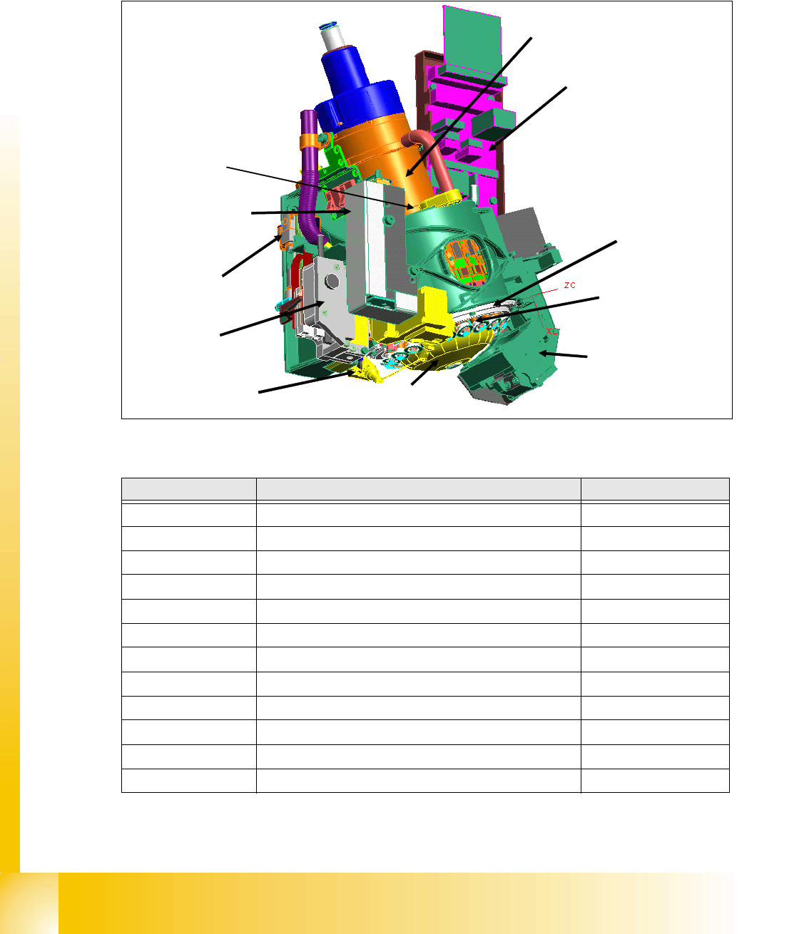
8.1.3 Parts overview with describtion
The following chapter described the main parts of the C&P20 Head and their technical function.
The sequence of the description is the sequence of disasemble for service.
8
Fig. 8.1 - 2 C&P20 Head- Parts overview
8
Position in Description Rart-Nr.
1
Collect&Place 20-Head 03008827-0X
2
E/D transmitter 03007834-0X
3
Vacuum generator (Placement/Pick up circuit) 03005070-0X
4
Retract unit 03007696-0X
5
Z-Drive 03005155-0X
6
Component -Sensor 03006742-0X
7
Star motor 03005097-0X
8
Intermediate distributor 03005158-0X
9
Raceway 03013243-0X
10
DP- Drive 03005109-0X
11
Component Camera 03003426-0X
12
Silencer holding circuit 03005121-0X
Table 8.1 - 2 Parts overview C&P 20
(7)
(6)
(11)
(3)
(5)
(10)
(9)
(2)
(12)
(4)
(8)
1 - 7
Student Guide SIPLACE X
Edition 09/2005 8 Collect&Place-Head 20
7
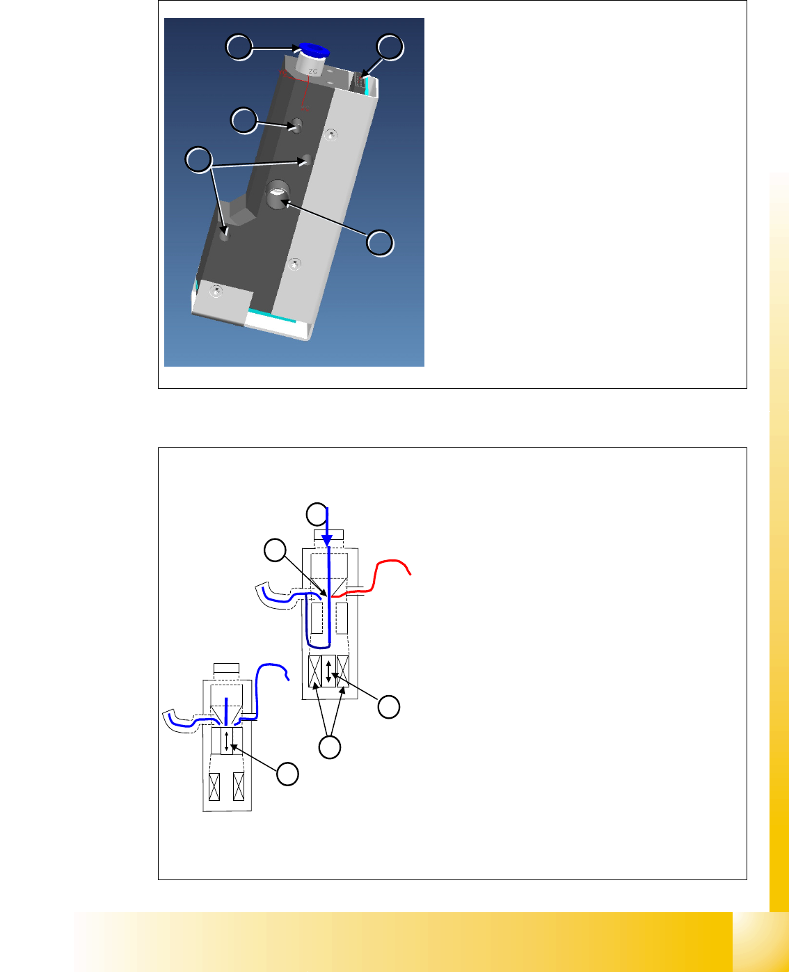
8.1.3.1 Vacuum generator
1
1
2
2
3
3
4
4
5
5
Vacuum generator (digital)
– The pressure control valve supplies the pickup
/
placement circuit with vacuum during the pickup
process and switches over to air kiss during
placement.
– This valve is fixed to the placement head with
two screws and can be replaced during service
work.
Vacuum generator Details
– Compressed air connection (1)
– Vacuum/air kiss (2) for pickup/placement circuit
– Discharged air
(3), for cooling the X linear motor
– Energy and data supply
(4)
– Mounting (5) for vacuum generator
4
2
1
3
2
Vacuum generator - Function
– After initialization, the piston is in a “central posi-
tion”, in which neither vacuum nor air kiss is ap-
plied to the nozzle.
– During pickup, the piston is always in the ‘open’
position, in which maximum vacuum is produced
and applied to the nozzle.
– The function “early vacuum” should always be
switched on for the C&P20 head.However, if this
function is switched off, the piston will start off by
being in the ‘open’ position and will then return to
the “central position” . The vacuum will only be
switched on again after the "light barrier down"
signal has been issued . -> 2 additional switching
steps -> time loss.
Vacuum generator Details
– Compressed air (1)
– Piston (2)
– Motor (3)
– Venturi nozzle (4)
1 - 8
Student Guide SIPLACE X
8 Collect&Place-Head 20 Edition 09/2005
8
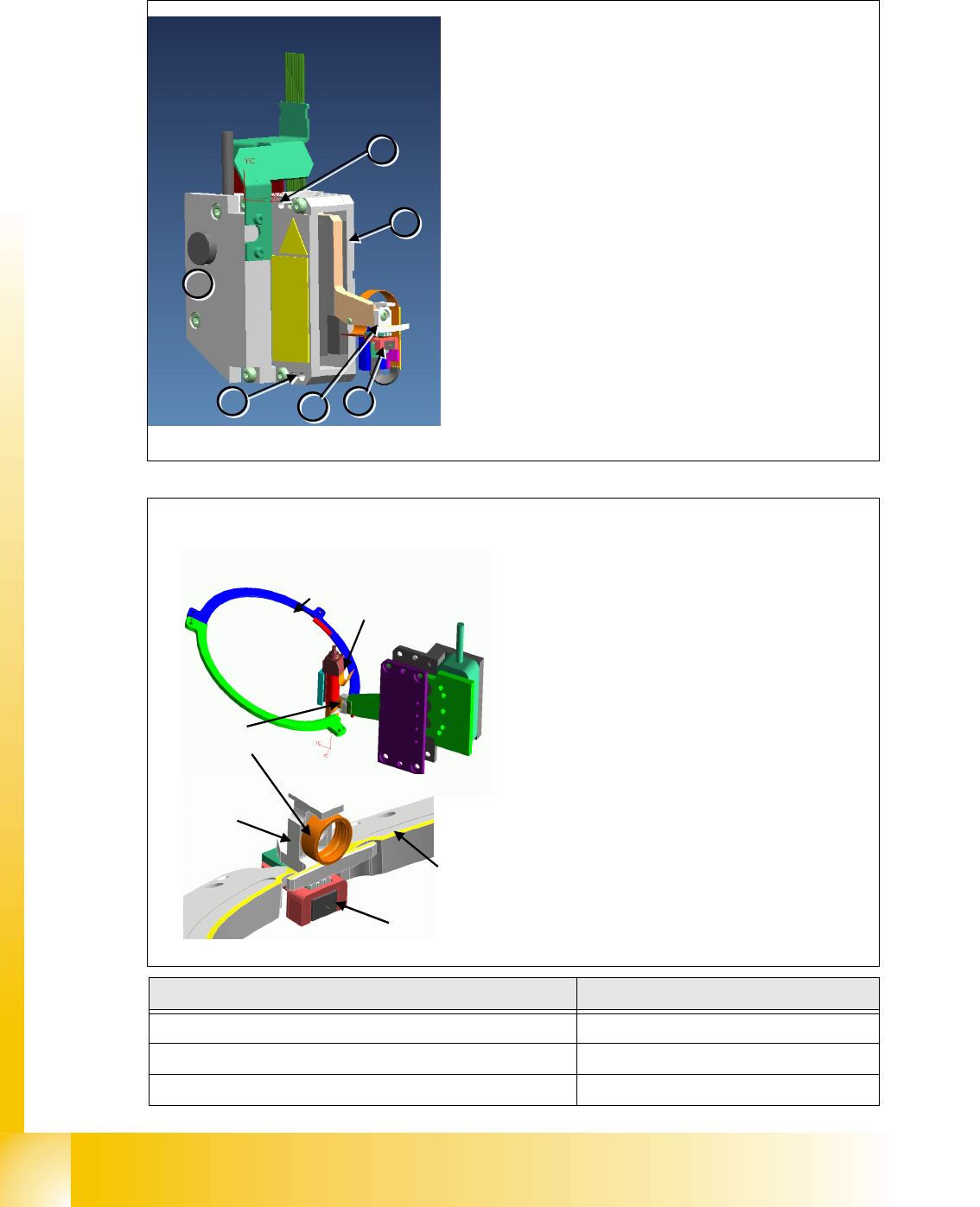
8.1.3.2 Z-Drive
Description Part No:
Z-Drive
03005155-0X
Z-Motor
03005183-0X
Light barrier "Z- Axis bottom"
03007833-0X
1
1
4
4
3
3
2
2
5
5
5
5
Z-Axis
– The Z-axis and retract unit are fixed to the head as a
complete unit, with two screws, and can be easily re-
placed during service work.
Z-Axis Unit Details
– Incremental measurement system (1) resolution
0,5µm.
– Linear motor, primary part
(2) moves between the
secondary parts up and down.
– Light barrier Z-down
(3) emits the end position sig-
nal for the Z-axis.
–Jaw
(4). The ball bearing for the DP drive is rotated
via the star axis into the jaw, allowing the segment to
be moved upwards and downwards.
– Mounting
(5) for Z-axis
Segment
ball bearings
Segment
Raceway
Jaw
Raceway
Light barrier
Z-down
Z-Drive - Function
– The jaws are installed on the primary part of
the Z-motor, for mechanical docking of the
segments.
– A Z-bottom sensor is located in the place-
ment position, for recognition of the Z-axis
put-on position. This recognizes a relative
movement between the nozzle and DP seg-
ment. When the Z-axis springs into place, this
sensor sends a signal to the axis card.The
"light barrier down" signal is directly linked to
the measurement signal of the Z-axis incre-
mental encoder.