SiplaceX4_en.pdf - 第452页
1 - 20 S tudent Guide SIPLACE X 9 Component handling Edition 09/2005 20 9.3.2 Part s of the X- Feeder (front view) Fig. 9.3 - 2 Parts on the X- feeder (Front view) 1. Locking roll (The locking hook of the com- ponent t a…

1 - 19
Student Guide SIPLACE X
Edition 09/2005 9 Component handling
19
9.3 X- Feeder
9.3.1 General
Fig. 9.3 - 1 main view - X- Feeder
Performance : 9
– Increased demand for speed at C&P20- head (Communication, dynamics 40ms for 4mm),
Feeder should not limit placement (communication, transport)
Precision : 9
– Designed for smallest components currently on the market
Reliability: 9
– Reliable drive system, "Closed loop" drive regulation, new mechanical interface, new electrical
interface, brushless DC- motors, optimised gear
Flexibility : 9
– Different pitches adjustable, "Hot- swaping" possible, Upgrade per Firmware- Download pos-
sible with station software, Adaptable to "problematic tapes", free step width, variable speed
profiles
Usability : 9
– Single track feeder, Tape loading, Interface to operator, Integrated Splice recognition (op-
tional), Able to handle sticky tapes (optional PSA kit (pressure sensitive adhesive)), no con-
nectors and cables, operator panel
Intelligence : 9
– Unique feeder- ID, Management data (cycles, power up hours, errors,...), Object data are
stored in set- up control data base
Robustness : 9
– No "on mechanical end stops" --> controlled movement of the transport
1 - 20
Student Guide SIPLACE X
9 Component handling Edition 09/2005
20
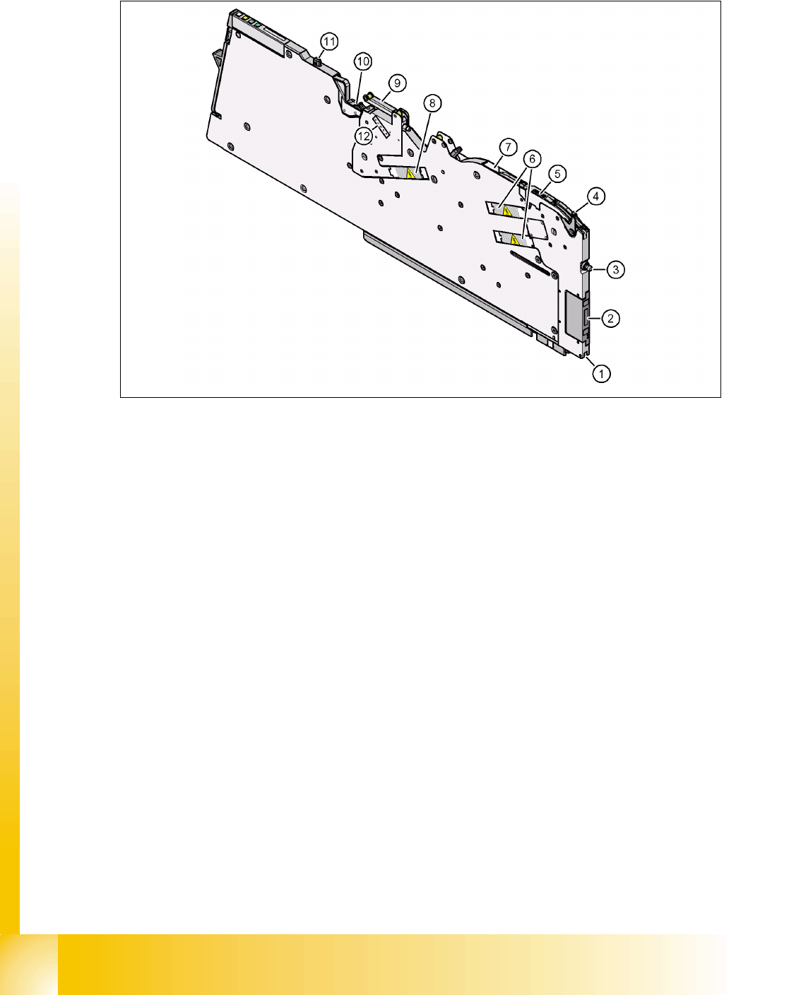
9.3.2 Parts of the X- Feeder (front view)
Fig. 9.3 - 2 Parts on the X- feeder (Front view)
1. Locking roll (The locking hook of the com-
ponent table lock the feeder in the end
position.)
2. Power- and Datainterface
3. Centering pin "front" 4. Lever to lift the Pickup window to insert
and remove the tape
5. Pick up window 6. Drive motors for tape transport
7. Opening of the tape channel 8. Drive motor for the cover foil unit
9. Cover foil rocker 10.Foil removal unit
11.Centering pin "back" 12.Adjustment of the cover foil tension
1 - 21
Student Guide SIPLACE X
Edition 09/2005 9 Component handling
21
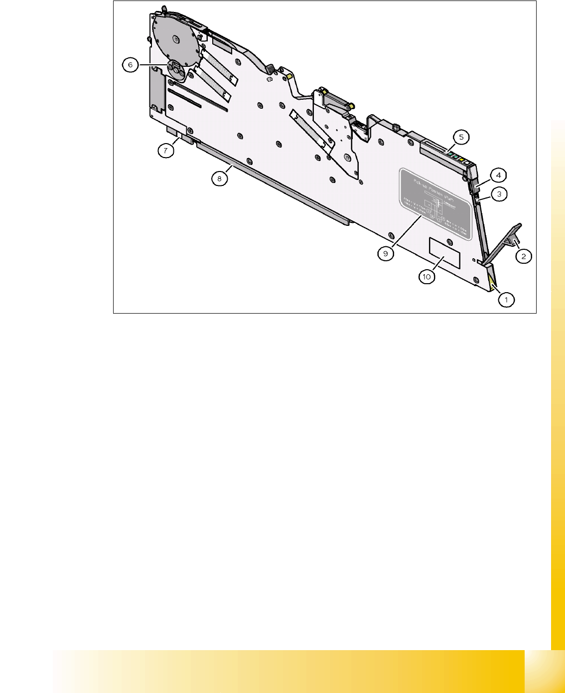
9.3.3 Parts of the X- Feeder (back view)
Fig. 9.3 - 3 Parts of the X-feeder
1. Entry aperture to the tape feed channel
with tape spring
2. Cover for the foil container
3. Foil container with cutter, to cut the foil 4. Button, to remove the feeder
5. Operator panel 6. Shutter for component removal
7. Guidance feeder at the component table
(front)
8. Guidance feeder at the component table
(back)
9. Label which described the different pick
up positions depend on the component
size
10. Data plate