SiplaceX4_en.pdf - 第84页
1 - 8 S tudent Guide SIPLACE X 3 Communication and Control Edition 09/2005 8 3.3.2.1 1 1 Bit Identifier The CAN bus s ystem is using t he 1 1 Bit identifier fo r addressing the different CAN obje cts Fig. 3.3 - 6 1 1 bit…
1 - 7
Student Guide SIPLACE X
Edition 09/2005 3 Communication and Control
7
3.3.2 CAN Bus in General
– CAN is a serial bus system especially suited for networking devices as well as sensors and
actuators within a system or subsystem.
– It is a bus system with multi-master capabilities, therefore all CAN nodes can request the
bus simultaneously.
– In CAN networks, there is no addressing of subscribers or stations in the conventional
sense, but instead, prioritized messages are transmitted. A transmitter sends a message to
all CAN nodes (broadcasting). Each node decide on the basis of the identifier received
whether it should process the message or not. The identifier determines the priority that the
message enjoys in competition for bus access. The relatively simplicity of the CAN chips
intergration make applications programming relatively simply.
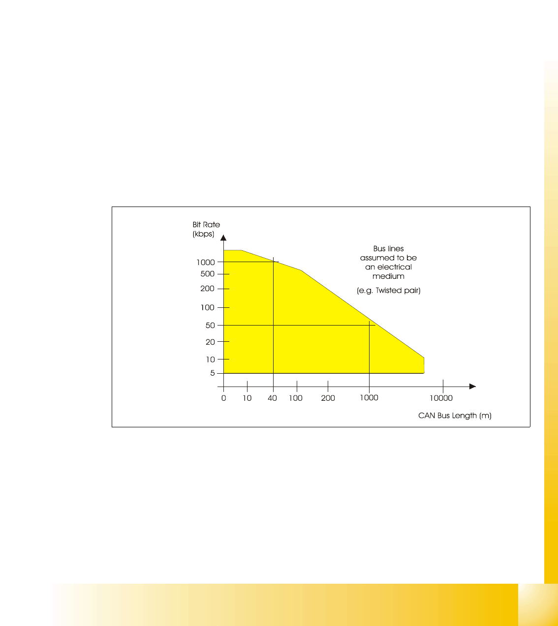
– Each CAN message can transmit from 0 to 8 bytes of user information. Of course, you can
transmit longer data information by using segmentation. The maximum transmission rate is
specified as 1 Mbit/s. This value applies to networks about 40 m. For longer distances the
data rate must be reduced:
For distances up to 500 m a speed of 125 kbit is possible and for transmissions up to 1 km
a data rate of 50 kbit/s is permitted.
3
I
Fig. 3.3 - 5 CAN -bus length
The maximum CAN bus speed is 1 MBaud, which can be achieved with a bus length of up to 40
meters when using a twisted wire pair. For bus lengths longer than 40 meters the bus speed must
be reduced. A 1000 meter bus can still be released with a 50 KBaud bus speed. For a bus length
above 1000 meters special drivers should be used.
1 - 8
Student Guide SIPLACE X
3 Communication and Control Edition 09/2005
8
3.3.2.1 11 Bit Identifier
The CAN bus system is using the 11 Bit identifier for addressing the different CAN objects
Fig. 3.3 - 6 11 bit identifier
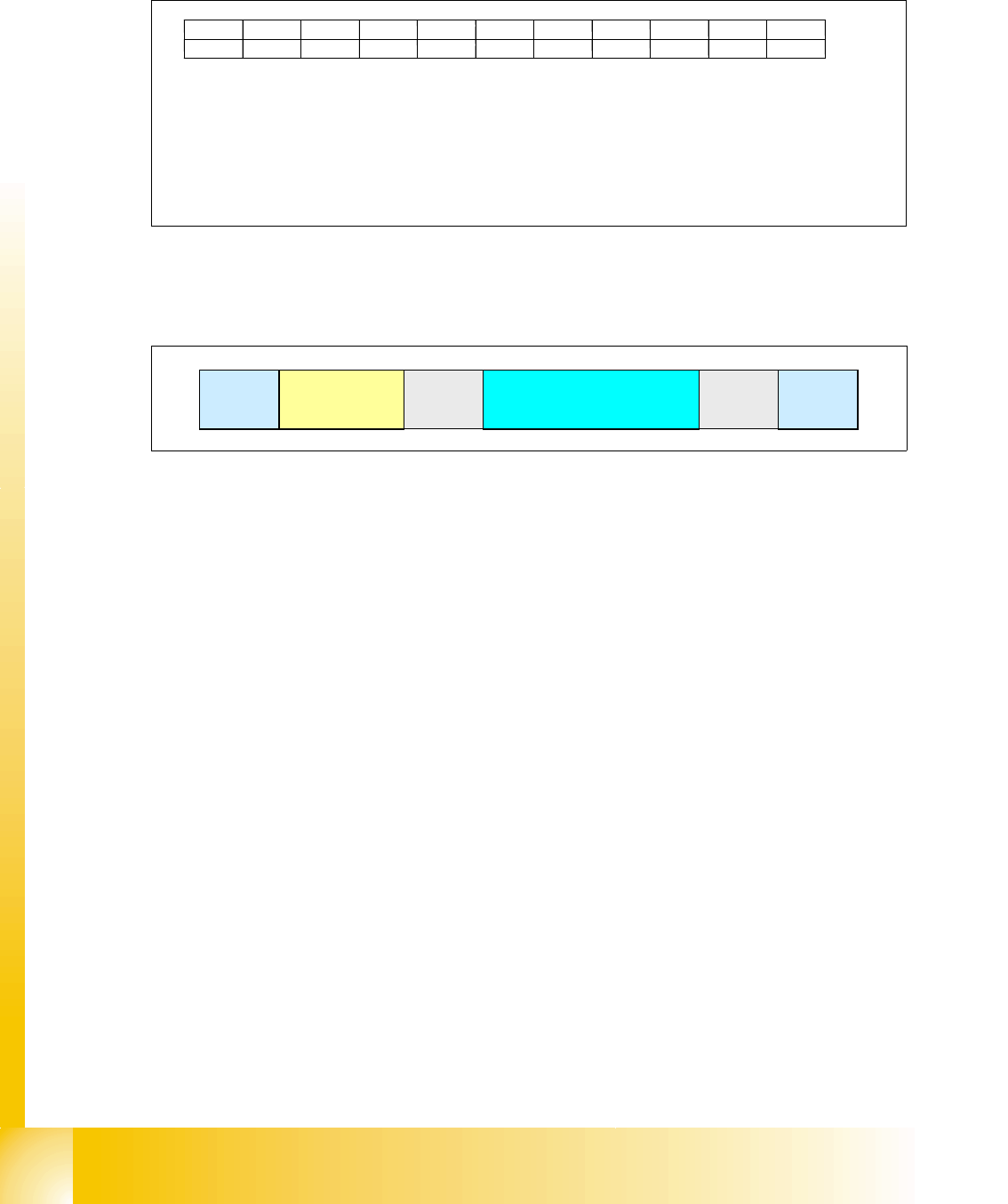
3.3.2.2 CAN Bus protocol
Fig. 3.3 - 7 CAN-bus protocol
Start: 3
– Determines the telegram start. After this bit is set, no other user of the CAN bus is able to
send. Even 2 or more user set this bit at the same time, the arbitration decides the highest
priority. The address with the highest priority is allowed to send the telegram.
Address: Identifier field (11 bit identifier) 3
– The value of this number is also the prority for the bus access.
Control information:
3
– Contains reserved bits and 4 bit DLC: Data Length Code.
Data field:
3
– Contains the user information from 0 byte to maximun 8 byte. The transfer of a byte begins
with the most significant bit (the bit with the highest value).
CRC sequence and CRC delimiter = CRC filed (cyclic redundancy check): 3
– Each message is combined with a CRC word. Therefore it recognizes messages which are
at least not in an origin state while disturbances.
End:
3
– The end of the length recognition is 7 bit.
Bit 10 Bit 9 Bit 8 Bit 7 Bit 6 Bit 5 Bit 4 Bit 3 Bit Bit 1 Bit 0
KKCCCCPPTTT
node type (K) CAN object (C) gantry number (P) telegram type (T)
depends on 00: section 1 000 command
node type 01: section 2 001 message
10: section 3
11: section 4
00: heads
01: axis
10: co table
11: reserved
start
address
(11 bit identifier)
control
information.
data (0-8 bytes user information) CRC
end
1 - 9
Student Guide SIPLACE X
Edition 09/2005 3 Communication and Control
9
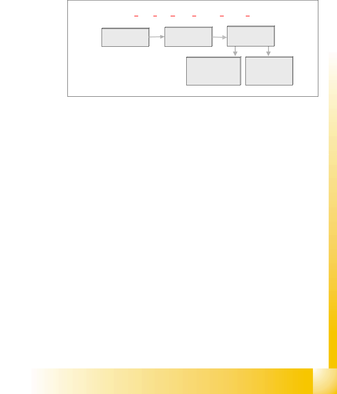
3.3.2.3 CSMA: Collusion Detectection
When the bus is free any unit may start to transmit a message. The unit with the message of the
highest priority is at first.
h
Fig. 3.3 - 8 CSMA: collusion detection
3.3.2.4 CAN Bus Arbitration
In CAN networks, there is no addressing of subscribers or stations in the conventional sense, but
instead, prioritized messages are transmitted. A transmitter sends a message to all CAN nodes
(broadcasting). Each node decide on the basis of the identifier received whether it should process
the message or not. The identifier determines the priority that the message enjoys in competition
for bus access. The relatively simplicity of the CAN chips interlaces make applications program-
ming relatively simply.
Whenever the bus is free, any unit may start to transmit a message. If 2 or more units start trans-
mitting messages at the same time, the bus access conflict is resolved by bitwise arbitration using
IDENTIFIER.
The mechanism of arbitration guarantees that neither information nor time is lost. A DATA FRAME
prevails over the REMOTE FRAME. During arbitration every transmitter compares the level of the
bit transmitted with the level that is monitored on the bus. If these levels are equal the unit may
continue to send. When a recessive level is sent and a dominant level is monitored, the unit has
lost arbitration and must withdraw without sending one more bit.
Multi master:
When the bus is free any unit may start to transmit a message. The unit with the message of the
highest priority is transmitted at first.
bus access
low waiting time
for high prioritized
telegrams
CSMA / CD: Carrier Sense Multiple Access by Collusion Detection
in case of collusion,
the members with
the lower priority
start again later
Carrier Sense
Multiple Access
(CSMA)
ollision
C
Detection
(CD)