SiplaceX4_en.pdf - 第187页
1 - 41 S tudent Guide SIPLACE X Edition 09/2005 4 Servic es to the machine 41 4.3.3.7 Pneumatic loop Cooling Y - Linear motor for Placement area 1/2 For the purpose of cooling the Y - motors an additio nal pneumatic syst…
1 - 40
Student Guide SIPLACE X
4 Services to the machine Edition 09/2005
40
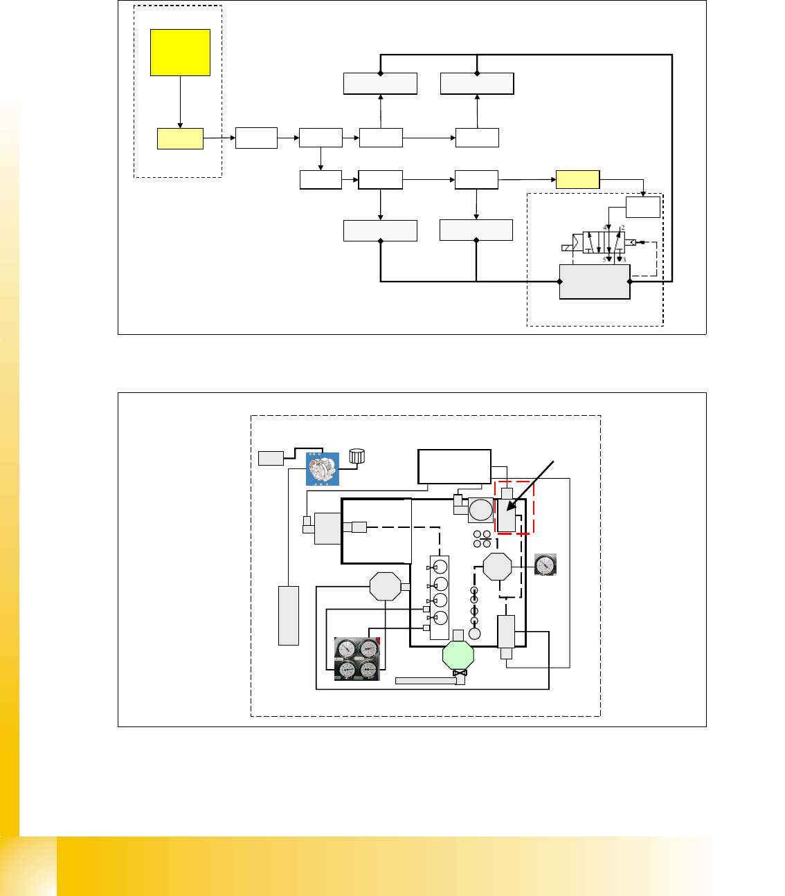
4.3.3.6 Safety valve X60
Safety valve for controlling the compressed air for transport and tape cutter. Air supply for trans-
port and tape cutter is only present, after the start button is pressed and all safety requirements
are fullfilled (safety loop closed).
Fig. 4.3 - 10 safety valve tape cutter
Fig. 4.3 - 11 safety valve location in main pneumatic unit
X2qa
X71qa X22qa
tape cutter 3
X17qa
tape cutter 2
SSK
X16
X71ra X22ra
tape cutter 4
X17ra
tape cutter 1
X21ra
2
4
V
power supply
24 V
5+0.1 bar
tape cutter
safety valve
5+0.1 bar
5+0.1 bar
main pneumatic unit
X60
main pneumatic unit
safety valve
1 - 41
Student Guide SIPLACE X
Edition 09/2005 4 Services to the machine
41
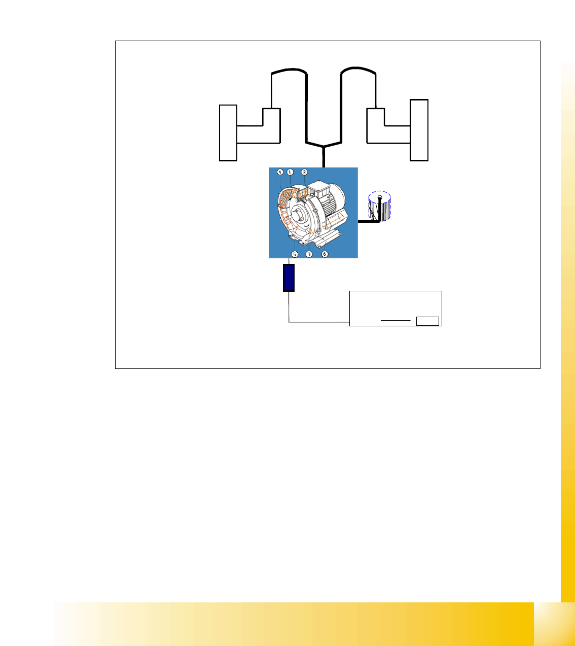
4.3.3.7 Pneumatic loop Cooling Y - Linear motor for Placement area 1/2
For the purpose of cooling the Y-motors an additional pneumatic system is integrated, which suck
the air from the environment, compress it by a compressor and blows it through a hose system to
each of the y-axis motor. The compressed air releases the motor on a lateral point.
The temperature of the Y-axis coils is monitored and when it exeeds 110 C, a message appears
at the monitor. To be very sure, the Y-axis does not get overheatet, is the reason for this simple
cooling system.
Fig. 4.3 - 12 cooling system Y-axis motor
Legend valid for HF:
1. compressor, located in main unit
2. start up unit for compressor
3. Y-axis motor placement area 2
4. Y-axis motor placement area 1
5. air hose for air supply used for cooling the linear motor
Power supply
X3_1
motor for
generating
compressed air
Y-motor BB1
Y-motor BB2
air hose
air hose
motor
"Start up" unit
F14
03003566
Filter
2
3
1
5
4
1 - 42
Student Guide SIPLACE X
4 Services to the machine Edition 09/2005
42
4.3.3.8 Pneumatic loop Cooling X - Linear motor for Placement area 1
For cooling the X-motors the exhausting air of the vacuum generator of C&P head and Twin head
is used. The cooling system for the Twin head in placement area 2 is quite similar. to the y-axis
cooling system. The major difference is the air distributor, which spread the air from both sides to
the x-axis on Twin head.
Fig. 4.3 - 13 cooling system X-axis motor
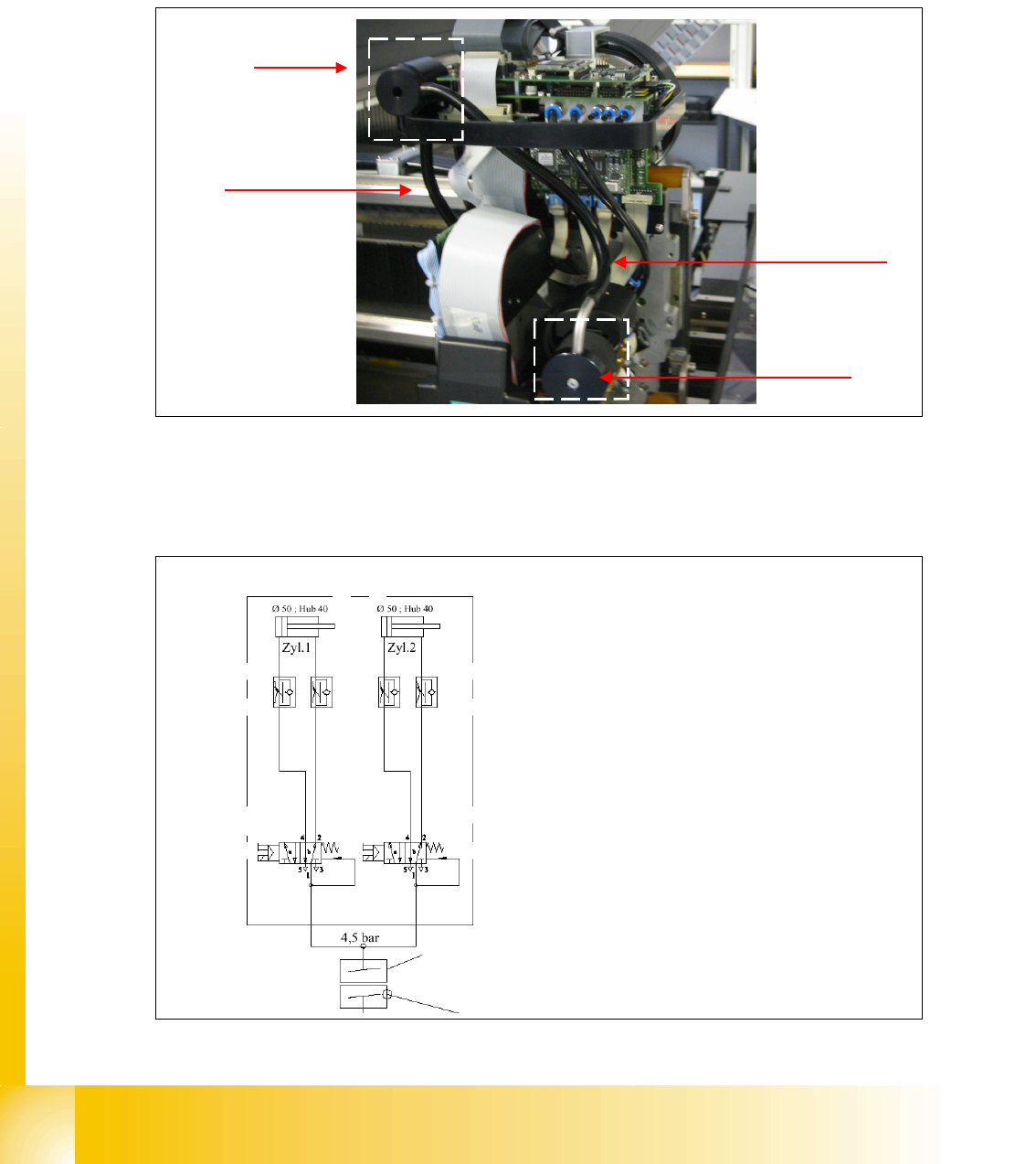
4.3.4 Pneumatic Supply Tape Cutter
Fig. 4.3 - 14 pneumatic supply tape cutter
air distributor
silencer
air pipe for cooling
the x-axis
pipe for air supply
to distributor
3
2
1
4
Legend:
1: drive cylinder for cutting edge movement
40 mm
2: adjustable throttle according to the cylinder
3: 5/2 valve
4: air supply 5 bar switched with SSK (when
SSK is energized)
valve 1 valve 2
cylinder 1 cylinder 2