SiplaceX4_en.pdf - 第248页
1 - 20 S tudent Guide SIPLACE X 6 Collect &Place-He ad 6/12 Edition 09/2005 20 6.2.4 Completion of th e Z-axis Reference Run Fig. 6.2 - 6 Completion of the Z-axis reference run – The S tar-axis turns to 6250 digit(HF…
1 - 19
Student Guide SIPLACE X
Edition 09/2005 6 Collect &Place-Head 6/12
19
6.2.2 Preparing Z-axis Reference Run
Fig. 6.2 - 4 Preparing Z-axis reference run (6 C&P head)
The Z-axis runs to uppermost end stop. When stand still is detected the Z-axis runs down by 27
digits with reduced force.
This Z-axis position with reduced force enables the placement star to move into reference posi-
tion.
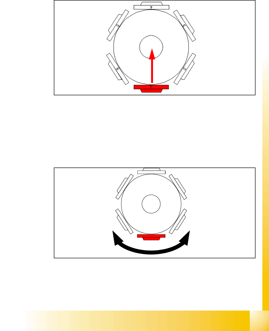
6.2.3 Reference Run at Star-Axis
Fig. 6.2 - 5 Reference run at star-axis
The star-axis turns counter clockwise to zero point pulse of the incremental shaft encoder. The
zero point correction is loaded. The star-axis turns clockwise (according the zero point correction)
until the position counter shows 0 digit.
Segment number 1 is now in pick-up / placement position.
4
1
5
2
3
6
1 - 20
Student Guide SIPLACE X
6 Collect &Place-Head 6/12 Edition 09/2005
20
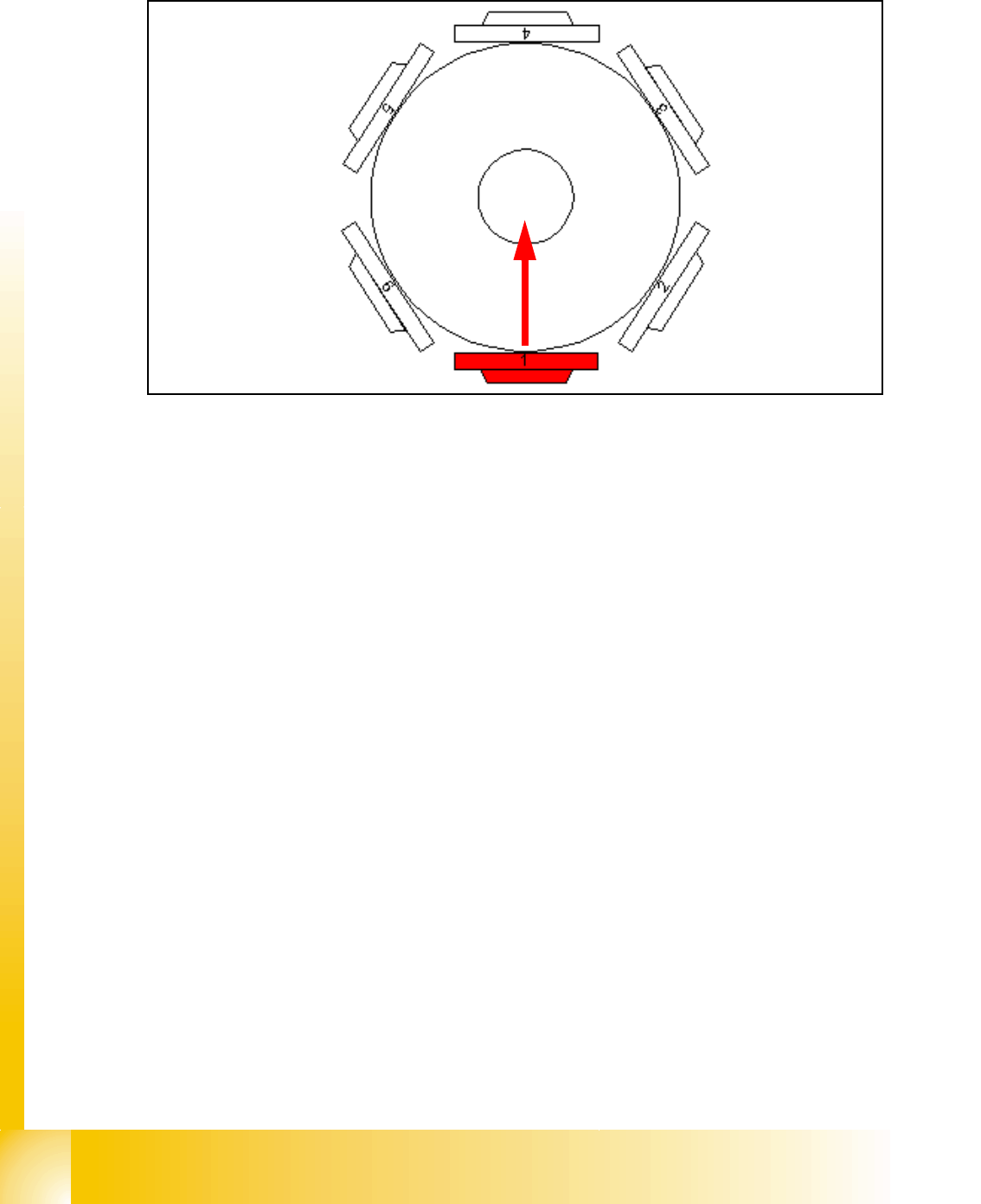
6.2.4 Completion of the Z-axis Reference Run
Fig. 6.2 - 6 Completion of the Z-axis reference run
– The Star-axis turns to 6250 digit(HF)2500(X4/X3/X2). At this position the segment ball bearing
is exactly between Z-claw and circular guidance.
– Z-axis moves to the upper end stop and takes the position. The same is done at the lower end
stop.
– The average value of these results is calculated and with a negative sign is loaded for refer-
ence value (ZPC) to the axis controller.
– Star-axis is moved back to reference position.
– Z-axis starts the reference run again with this new value.
1 - 21
Student Guide SIPLACE X
Edition 09/2005 6 Collect &Place-Head 6/12
21
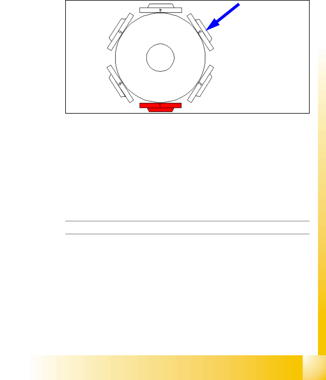
6.2.5 Reference Run at Dp-axis
The function of the DP axis is, to turn the nozzle in the correct pick up angle. After the component
recognition the DP-axis turn the components in correct placement angle.
Fig. 6.2 - 7 Reference run at DP-axis
– The segment now in the DP-station is turned to reference position. (Segment 3 at 6 nozzle
head / Segment 5 at 12 nozzle head.)
– Sequence: the DP-station swivels in. The axis starts and searches for the zero pulse. The Zero
pulse is checked on failure. The DP-station swivels out after the end signal.
– The swiveling function is controlled by the CAN-Bus.
– Turning the sleeve is controlled by the axis controller with signals from DP-position encoder.
– The zero point correction on the DP-axis is always 0 (because up to 12 segments are operated
by one drive).
C&P Head Reference run finished!