SiplaceX4_en.pdf - 第90页
1 - 14 S tudent Guide SIPLACE X 3 Communication and Control Edition 09/2005 14 3.3.6 CAN-Bus Concept with On e Wire Bus e.g. SiplaceX3 The placement machine SIPLACE HF/HF3 uses with the Software 505 an additional bus sys…
1 - 13
Student Guide SIPLACE X
Edition 09/2005 3 Communication and Control
13
3.3.5 CAN Bus Concept SiplaceX2
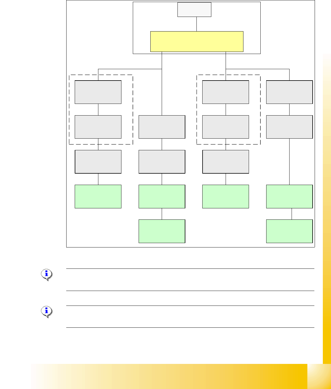
The placement machine SIPLACE HF3 uses a bus system with 1 Mbit/s transmission rate.The
CAN: Bus system begin at the Communication board and is split in 2 path. Every path is termi-
nated by a 120 ohm terminator on the head board at the individual placement head.
Fig. 3.3 - 13 CAN Bus overall overview HF3
Note: When the Twin head is mounted, the switch for the terminator on the head board (C500)
have to be OFF. 3
Please Note: If you work with the Caccia (Diagnose Tool), please switch OFF the machine before
you connect the cable.
SMP BUS
MC
MC
Computer Unit
C
O
M
U
n
i
t
CAN Bus cable
PA1
X6pn
Trailing Interface
Gantry 1
Transport
Control unit
COT 1
Tape cutter
CAN E/
A
Modu
l
Sektor
4
CAN E/
A
Modu
l
Sektor
4
CAN E/
A
Modu
l
Sektor
4
CAN I/O
SUB Modul
Sector 4
Vision
Control unit
Sector 4
COT 4 / MTC2
Tape cutter
SUB Distributor Sector 4
Terminator
120 Ohm
Head board(C500)
Gantry 1
Terminator
(120 OHM)
CAN Bus cable
PA 2
X7pn
Main Distributor Sector 2
COT 3
Tape cutter
Axis unit
PA 2
Vision
Control unit
Sector 2
CAN I/O
Main Modul
Sector 2
COT 2 / MTC2
Tape cutter
Trailing Interface
Gantry 3
Terminator
120 Ohm
Head board(C500)
Gantry 3
Terminator
(120 OHM)
1 - 14
Student Guide SIPLACE X
3 Communication and Control Edition 09/2005
14
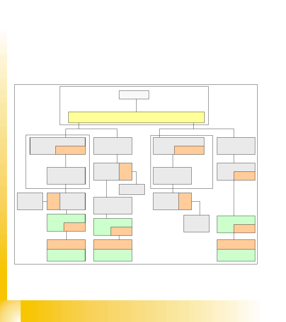
3.3.6 CAN-Bus Concept with One Wire Bus e.g. SiplaceX3
The placement machine SIPLACE HF/HF3 uses with the Software 505 an additional bus system,
which are integrated into the CAN Bus cable --> One Wire Bus.
With the Siplace X-machine the One Wire Bus is integreted in a separate CAT5 cabel, which start
from the Main- and Subdistributor up to the trailling interface. On the Main- and Subdistributor are
installed the control unit of the one wire system. A kind of switch are located on the other units
which required the one wire system (see figure below). This switch open and close the communi-
cation path.
Controlled components with the ONE Wire Bus:
– Nozzle changer of the C&P heads
– Temperature sensors
– Gantry recognition (CFK02, CFK04, CFK06)
– Option Reject Box
Fig. 3.3 - 14 General overview CAN-Bus with One Wire Siplace X3
Cat 5 (english category), is a Twisted-Pair-cabel, for data tranfer.
SMP BUS
MC
MC
Axis unit
PA 1
CAN Bus cable
Computer Unit
CAN E/
A
Modu
l
Sektor
4
CAN E/
A
Modu
l
Sektor
4
CAN E/
A
CAN I/O
SUB Modul
Sektor 4
COT 1
Tape cutter
SUB Distributor Sector 4
Main Distributor Sector 2
C
O
M
U
n
i
t
x
6
p
n
x
7
p
n
CAN Bus cable
One Wire
"Control unit"
One Wire
"Switch"
CAN Bus cable
with One Wire
COT 4
Tape cutter
Vision
Control unit
Sector 4
Trailing
cable-
Interface
Gantry 4
One Wire
"Switch"
Temperature sensor
Gantry recognition
One Wire
"Head interface"
Temperature sensor
Gantry recognition
One Wire
"Head interface"
Axis unit
PA 2
COT 3
Tape cutter
One Wire
Hub
One Wire
"Switch"
Temperature sensor
Gantry recognition
One Wire
"Head interface"
CAN I/O
Main Modul
Sector 2
One Wire
"Control unit"
CAN Bus cable
with One Wire
Transport
Control
unit
Nozzle
changer A/B
COT 2 / MTC
Tape cutter
Vision
Control unit
Sector 2
Nozzle
changer A/B
One Wire
Hub
One Wire
Hub
Nozzle
changer A/B
One Wire
Hub
Trailing
cable-
Interface
Gantry 1
Trailing
cable-
Interface
Gantry 3
1 - 15
Student Guide SIPLACE X
Edition 09/2005 3 Communication and Control
15
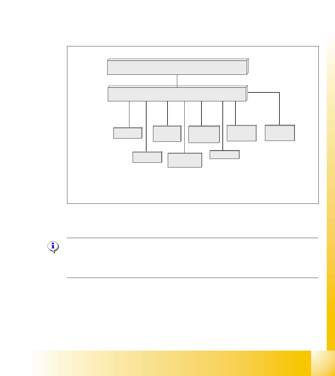
3.3.7 CAN Bus Processor Board C&P Head
Can bus processor board TQM 167 LC is mounted on the head board C500. The processor board
is used at different places in the machine.
If the processor board on the head board, the firmware provides at the processor board the control
of the head specific actors and sensors no matter which head type is installed.
3.3.7.1 CAN Bus controlled function on 6/12C&P Head
The following overview shows various head functions, controlled by the CAN system. Thus, the
CAN bus controls the actuators and sensors of the C&P Head.
Fig. 3.3 - 15 CAN function on C&P Head
NOTE:
The status of the 16 Bit PROCESSOR BOARD is indicated on the 7-segment display.
Normal status on the diplay is: Display shows slowly flashed " . "
(Description of the 7-segment display see chapter C&P Head).
Comp.-sensor
CAN Bus 16 bit Processor Board
stepper motor
reject
:
LS top
LS bottom solenoid valve
air kiss
:
CAN bus
stepper motor
swivel in Dp
stepper motor
pick up / place
Vacuum values
Communication Board
LS = Light barrier