SiplaceX4_en.pdf - 第391页
1 - 25 S tudent Guide SIPLACE X Edition 09/2005 8 Collect&Place-Head 20 25 8.2.7 Determining the V ac uum and Threshold V alues Fig. 8.2 - 7 Measuring and calculating t he vacuum values for a reference run 1. The vac…
1 - 24
Student Guide SIPLACE X
8 Collect&Place-Head 20 Edition 09/2005
24
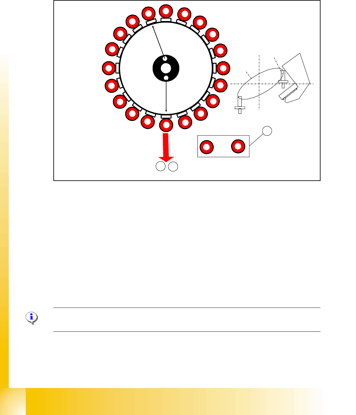
8.2.6 Vacuum Check Procedure
The vacuum check serves for control of soiled and damaged nozzles as well as for the check of
the nozzle types.
Fig. 8.2 - 6 Vacuum check procedure
– The gantry axes move the C&P head into the reject position to clean the nozzles before mea-
surement.
– The Star axes move in an anticlockwise direction and all cleaning functions are performed at
the same time, within one head cycle. (see Fig. 8.2 - 6).
(1) The DP drives rotate each segment into the 0° position.
(2) The digital pressure control valve now activates the air kiss for the reject position. The com-
ponents still on the nozzle will be rejected.
(3) The vacuum reference values (open/closed) are measured at the pickup/placement position
during the height reference run.
PLEASE NOTE:
In SIPLACE X machines, components are rejected in the pickup/placement position.
1
2
3
4
5
6
7
8
9
10
12
11
13
14
15
16
17
18
19
20
Segment 1
Segment 11
S
t
ar
p
o
s
i
t
i
o
n
CO- Camera
2
3
,
1
1
20
to
1 - 25
Student Guide SIPLACE X
Edition 09/2005 8 Collect&Place-Head 20
25
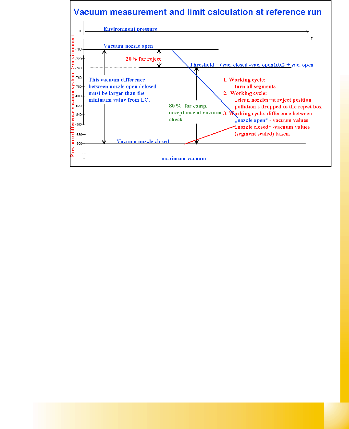
8.2.7 Determining the Vacuum and Threshold Values
Fig. 8.2 - 7 Measuring and calculating the vacuum values for a reference run
1. The vacuum is measured twice at the reference point: once with closed and once with open
state, at the top of the nozzle.
2. The value with closed valve depends not anymore on the ambient pressure it is controlled by
the pressure control valve. A influence to the vacuum values are the nozzle fit on the segment
and the quality f the nottle top and the surface of transport rail at height measurement position.
3. The value by open valve depends on the nozzle size and condition. The smaller the nozzle,
the greater the open valve value will be. A contaminated or blocked nozzle will also give a
higher valve.
4. The difference between the open and closed nozzles has been preset by the line computer as
an ideal case minimum value. This value is different for all nozzle types e.g. 120 mbar for 1004,
1014 nozzles. If these values are not achieved, the error message "vacuum difference open-
closed is too low" will appear.
5. The threshold for component acceptance is also set now. Assumed are following values of 660
mbar by open nozzle and 852 mbar by closed nozzle on the transport rail.
The calculation is as follows:
Vacuum distance = 852(closed) - 660(open)= 192 mbar (larger than the min. distance on
nozzle type parameter set.
Threshold (192 mbar x 0.2)+ 660 (open value) = 698,4 mbar
1 - 26
Student Guide SIPLACE X
8 Collect&Place-Head 20 Edition 09/2005
26
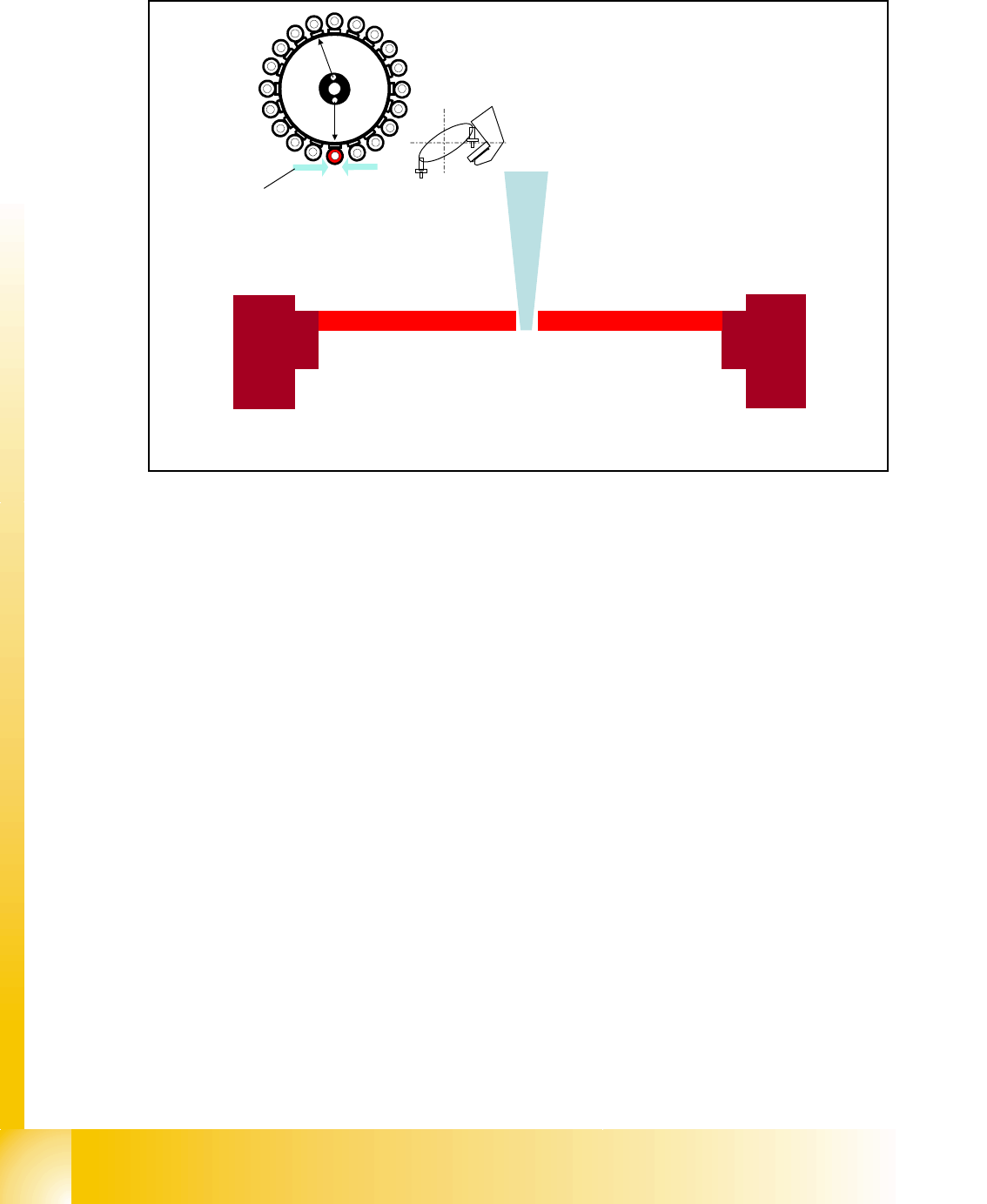
8.2.8 Measuring Z- axis position for Component Recognition by the Component
Sensor
Fig. 8.2 - 8 Nozzle length measurement at reference run for component recognition
During the height reference run the Component Sensor measures the Z axes position for each
segment, for detetecting the presence/absence of components in the pick up and placement po-
sition. During placement the Component Sensor can also recognize dirty nozzles.
While the Z axis moves downwards, the nozzle interrupts the IR beam of the Component sensor.
The axis position is saved and later used for the calculation of the component height and compo-
nent presence. At the upwards movement of the Z axis the IR beam is no longer interrupted and
the axis position is saved again. So the component presence can be determind during placement
by the programmed component height (Siplace Pro) and the nozzle length which was calculated
during the height reference run by the Z- axis position counter.
Receiver
LD - Transmitter
Nozzle
14
19
1
2
20
18
17
16
15
13
12
11
10
9
8
7
6
5
4
3
Component Sensor
LD LASER Diode