SiplaceX4_en.pdf - 第404页
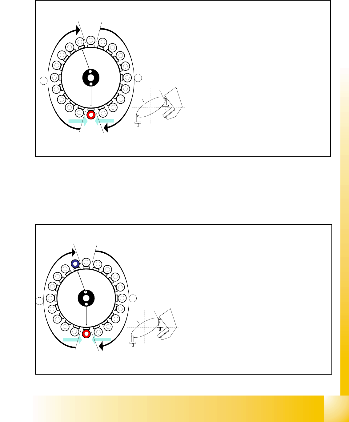
1 - 38 S tudent Guide SIPLACE X 8 Collect&Place-Head 20 Edition 09/2005 38 8.3.17 Placing the 1 1th Component Fig. 8.3 - 17 Placing the 1 1th component 8.3.18 Placing the 20th Component Fig. 8.3 - 18 Placing the 20th…
1 - 37
Student Guide SIPLACE X
Edition 09/2005 8 Collect&Place-Head 20
37
8.3.15 Component Sensor Checks Segment 1
Fig. 8.3 - 15 Component sensor checks after placement
The sequence described in Ch.8.2.13 to 8.2.15 is repeated for the remaining nozzles.
8.3.16 Placing the 10th Component
Fig. 8.3 - 16 Placing the 10th component
1
2
3
4
5
6
7
8
9
10
12
11
13
14
15
16
17
18
19
20
Segment 1
Segment 11
S
t
a
r
p
o
s
i
t
i
o
n
CO- Camera
CO - Sensor
CO- Sensor
A
B
Sternposition 0°
– Vision system: optical centering of the 11th com-
ponent.
– Pickup/placement station:
Z-axis moves upwards and sensor checks
whether component has been placed at seg-
ment 1.
–
A, B (see previous chapter).
– Vacuum check: whether vacuum has been
switched back on.
10
CO - Sensor
CO - Sensor
Segment 10
Segment 20
S
t
a
r
p
o
s
i
t
i
o
n
CO- Camera
1
2
3
4
5
6
7
8
9
11
12
13
14
15
16
17
18
19
20
A
B
Star position 162°
– Vision system: optical centering of the 20th compo-
nent
– Pickup / placement station: place 10th component.
(marked red (light grey) here)
– At the next step Visionsystem have to center opti-
cally the component at segment 1 on the other gan-
try. (marked blue here)
– Component sensor:
Checks before placement; if component is present
on nozzle / after placement; if the component has
been placed.
(see Ch. 8.2.13 to 8.2.15)
– A, B (see previous chapter)
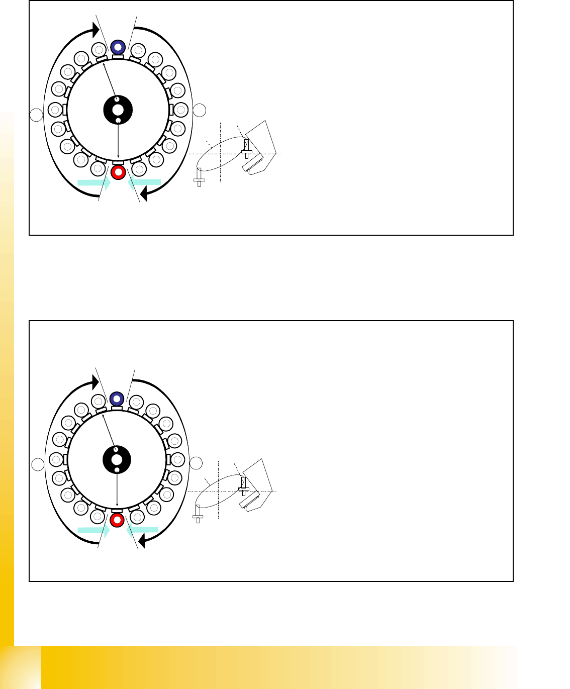
1 - 38
Student Guide SIPLACE X
8 Collect&Place-Head 20 Edition 09/2005
38
8.3.17 Placing the 11th Component
Fig. 8.3 - 17 Placing the 11th component
8.3.18 Placing the 20th Component
Fig. 8.3 - 18 Placing the 20th component
CO- Sensor
CO - Sensor
Segment 11
Segment 1
S
t
a
r
p
o
s
i
t
i
o
n
CO-Camera
11
12
13
14
15
16
17
18
19
1
2
3
5
6
7
8
9
10
4
20
A
B
Star position 180°
– Vision system: optical centering of the 1st comp
o
on the other gantry (marked blue here)
– Pickup / placement station: place 11th compon
e
(marked red (light grey) here)
– Component sensor:
Checks before and after placement, whether
component is present on nozzle / has been placed
.
(see Ch. 8.2.13 to 8.2.15)
– A, B (see previous chapter)
CO - Sensor
CO - Sensor
Segment 20
Segment 10
S
t
a
r
p
o
s
i
t
i
o
n
CO-Camera
9
8
7
6
5
4
3
2
1
19
18
17
15
14
13
12
11
10
16
20
A
B
Star position 342°
– Vision system: optical centering of the 10th com-
ponent on the other gantry (marked blue here)
– Pickup / placement station: place 20th compo-
nent. (marked red here)
– Component sensor:
Checks before and after placement, whether
component is present on nozzle/has been
placed.
(see Ch. 8.2.13 to 8.2.15)
– A, B (see previous chapter)
– Synchronization:
After the 20th component this gantry Y-Axis con-
troller will enable the other gantry Y-Axis to move
to 1st placement position.

1 - 39
Student Guide SIPLACE X
Edition 09/2005 8 Collect&Place-Head 20
39
8.3.19 Pickup and Placement Cycle for the Next Components...
– After all the components of the first head cycle have been placed on the board, the gantry axes
move the placement head to the pick up position of the next pick up cycle.
– The next pick up cycle for components 21 to 40 is executed.
– And so on and so on..... If necessary the machine executes repair cycles.
8.3.20 Segment with a „Defective Component“
If the optical centering of a component fails (ident. error) or component recognition before place-
ment fails, the component will not be placed and will remain on the nozzle.
– the turning station will still turn this nozzle to the pick up angle of the new component if this
segment is in area
A.
If this segment is in pick up position:
– The reject procedure will be activated and
– The X/Y axes will move to the reject position for that gantry,
– The component will be rejected to the reject box below, via air kiss
– The gantry is moved back to the pick up position.
– The new component will be picked up.
This rejected component will be placed during a „repair cycle“, after all the placement cycles set
for the placement head have been performed.
8.3.21 Finishing PCB Placement
– After placing the last component with the C&P20 head the gantry axes move the placement
heads to the waiting position.
– After the first board, or the one, respective to Scan parameter, a optical nozzle scan on pollu-
tion is executed,
– The SIPLACE placement station activates the transport system and moves the board to the
intermediate/output conveyor.
– Finally, the SIPLACE placement station sends the number of consumed components (placed
and rejected ones) to the computer with the OIS (Operator Information System).
– The OIS (Operator Information System) calculates the placement statistics referring to the pro-
grammed station setup, the programmed cluster or the last reset time. These placement sta-
tistics help to optimize the production process.
– The machine is now ready for the next board.