SiplaceX4_en.pdf - 第568页
1 - 1 S tudent Guide SIPLACE X Edition 09/2005 13 MTC 2 1 13 MTC 2 13.1 Overview 13.1.1 General Matr ix T r ay Changer 2 The MTC 2 shows a unit that as a whole as a move able component cha ngeover tab le can be re- place…

1 - 2
Student Guide SIPLACE X
Contents Edition 09/2005
2
13.2.8.1 Main view with MTC 2. . . . . . . . . . . . . . . . . . . . . . . . . . . . . . . . . . . . . . . . . . . . 29
13.2.8.2 "Matrix-tray changer" view . . . . . . . . . . . . . . . . . . . . . . . . . . . . . . . . . . . . . . . . 31
13.2.9 Single functions of the MTC 2 . . . . . . . . . . . . . . . . . . . . . . . . . . . . . . . . . . . . . . . . . 34
13.2.9.1 "Matrix-tray changer single functions" view . . . . . . . . . . . . . . . . . . . . . . . . . . . 34
13.3 Calibration MTC 2. . . . . . . . . . . . . . . . . . . . . . . . . . . . . . . . . . . . . . . . . . . . . . . . . . . . . . . . . . . . . . 35
13.3.1 Calibration sequence in general . . . . . . . . . . . . . . . . . . . . . . . . . . . . . . . . . . . . . . . 35
13.3.1.1
Terms of calibration lifting axes . . . . . . . . . . . . . . . . . . . . . . . . . . . . . . . . . . 36
13.3.1.2 Terms of calibration feed axes . . . . . . . . . . . . . . . . . . . . . . . . . . . . . . . . . . . . . 37
13.3.2 Sitest calibration flow charts . . . . . . . . . . . . . . . . . . . . . . . . . . . . . . . . . . . . . . . . . . 38
13.3.2.1 Lifting axes . . . . . . . . . . . . . . . . . . . . . . . . . . . . . . . . . . . . . . . . . . . . . . . . . . . . 38
13.3.2.2 Feed axes. . . . . . . . . . . . . . . . . . . . . . . . . . . . . . . . . . . . . . . . . . . . . . . . . . . . . 39
13.3.2.3 Machine data MTC . . . . . . . . . . . . . . . . . . . . . . . . . . . . . . . . . . . . . . . . . . . . . . 46
13.3.3 Adjustments Lifting Axes . . . . . . . . . . . . . . . . . . . . . . . . . . . . . . . . . . . . . . . . . . . . . 47
13.3.3.1 Belt tension. . . . . . . . . . . . . . . . . . . . . . . . . . . . . . . . . . . . . . . . . . . . . . . . . . . . 48
13.3.3.2 Guide rails and stopper bars. . . . . . . . . . . . . . . . . . . . . . . . . . . . . . . . . . . . . . . 51
13.3.3.3 Cassette guide rails . . . . . . . . . . . . . . . . . . . . . . . . . . . . . . . . . . . . . . . . . . . . . 53
13.3.4 Adjustments feed axes . . . . . . . . . . . . . . . . . . . . . . . . . . . . . . . . . . . . . . . . . . . . . . 54
13.3.4.1 Belt tension. . . . . . . . . . . . . . . . . . . . . . . . . . . . . . . . . . . . . . . . . . . . . . . . . . . . 55
13.3.4.2 Limit switch . . . . . . . . . . . . . . . . . . . . . . . . . . . . . . . . . . . . . . . . . . . . . . . . . . . . 57
13.3.4.3 Light barriers. . . . . . . . . . . . . . . . . . . . . . . . . . . . . . . . . . . . . . . . . . . . . . . . . . . 58
13.3.4.4 Checking and setting the WTC safety queries . . . . . . . . . . . . . . . . . . . . . . . . . 60
13.3.4.5 Disengaging mechanism . . . . . . . . . . . . . . . . . . . . . . . . . . . . . . . . . . . . . . . . . 63
13.3.5 Converting the power supply . . . . . . . . . . . . . . . . . . . . . . . . . . . . . . . . . . . . . . . . . . 64
13.3.5.1 Procedure . . . . . . . . . . . . . . . . . . . . . . . . . . . . . . . . . . . . . . . . . . . . . . . . . . . . . 64
13.3.5.2 Voltage distributor terminal X01 . . . . . . . . . . . . . . . . . . . . . . . . . . . . . . . . . . . . 65
13.3.5.3 Motor protection switch. . . . . . . . . . . . . . . . . . . . . . . . . . . . . . . . . . . . . . . . . . . 65
13.3.6 Machine Data. . . . . . . . . . . . . . . . . . . . . . . . . . . . . . . . . . . . . . . . . . . . . . . . . . . . . . 66
13.3.6.1 General machine parameters . . . . . . . . . . . . . . . . . . . . . . . . . . . . . . . . . . . . . . 66
13.3.6.2 Machine parameters for tower 1 . . . . . . . . . . . . . . . . . . . . . . . . . . . . . . . . . . . . 66
13.3.6.3 Machine parameters for tower 2 . . . . . . . . . . . . . . . . . . . . . . . . . . . . . . . . . . . . 67
13.3.7 Description of the LED terminal strips X04 and X05 . . . . . . . . . . . . . . . . . . . . . . . . 68
13.3.8 Spare parts list for MTC1. . . . . . . . . . . . . . . . . . . . . . . . . . . . . . . . . . . . . . . . . . . . . 70
13.4 Masterdrives . . . . . . . . . . . . . . . . . . . . . . . . . . . . . . . . . . . . . . . . . . . . . . . . . . . . . . . . . . . . . . . . . . 71
13.4.1 Operating the master drive with the parametrization unit (PMU). . . . . . . . . . . . . . . 71
13.4.2 Important Parameter for trouble shooting . . . . . . . . . . . . . . . . . . . . . . . . . . . . . . . . 72
13.4.3 Factory settings . . . . . . . . . . . . . . . . . . . . . . . . . . . . . . . . . . . . . . . . . . . . . . . . . . . . 73
13.4.4 Setting the CAN bus address at the master drive PMU. . . . . . . . . . . . . . . . . . . . . . 74
13.4.5 Downloading parameter sets . . . . . . . . . . . . . . . . . . . . . . . . . . . . . . . . . . . . . . . . . . 77
13.4.6 Error messages issued via the station. . . . . . . . . . . . . . . . . . . . . . . . . . . . . . . . . . . 85
1 - 1
Student Guide SIPLACE X
Edition 09/2005 13 MTC 2
1
13 MTC 2
13.1 Overview
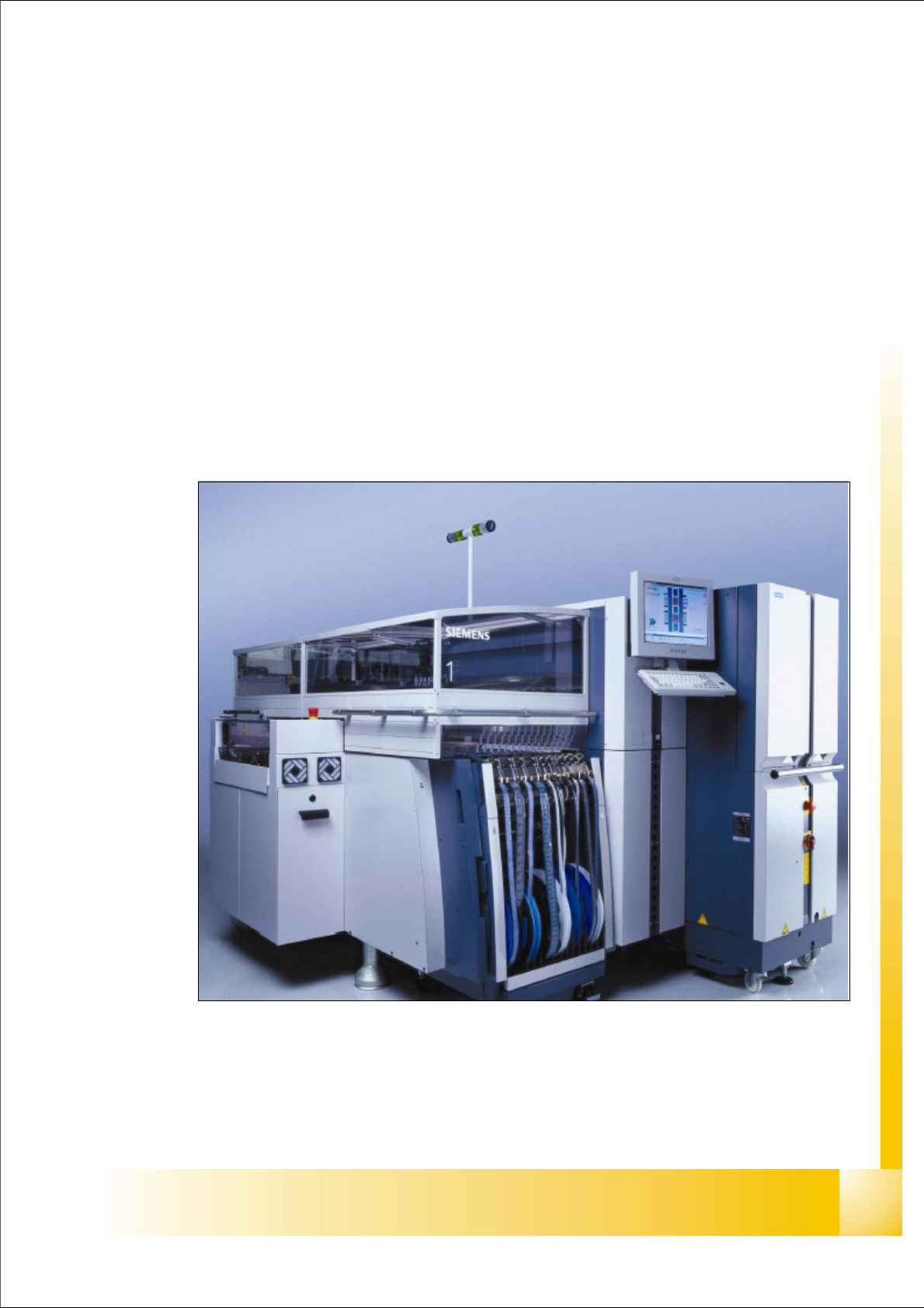
13.1.1 General Matrix Tray Changer 2
The MTC 2 shows a unit that as a whole as a moveable component changeover table can be re-
placed.
The MTC 2 was developed for the machine generation Siplace HF/HF3 and furthermore can be
installed to the machine generation Siplace X.
Depend the machine configuration, can the MTC 2 docked at location 2/4 (Siplace X2) and only
at location 2 at the Siplace X3 machine.
Fig. 13.1 - 1 Siplace machine with MTC 2 at location 2
1 - 2
Student Guide SIPLACE X
13 MTC 2 Edition 09/2005
2
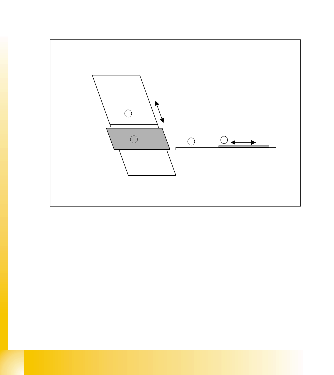
13.1.2 Functional principles
The MTC 2 has two towers which work independently of each other. They each have a lifting axis
and a feed axis. The lifting axes can be set up with a large number of waffle pack trays in cassettes
and transport these vertically. The feed axes transport waffle pack trays which have been set up
horizontally to the pick-up position of the SIPLACE station.
The waffle pack trays (WPT) to be set up are placed in waffle pack tray carriers (WTC). They are
then inserted in a cassette one above the other with a small gap between each of them, and fixed
in place with the WTC interlock. The cassettes are fixed in place in the tower with the cassette
interlock.
Fig. 13.1 - 2 Functional principles of the MTC 2
Key
1. Lifting axis
2. Cassette with WTCs
3. Feed axis
4. WTC on the feed axis
1
2
3
4