SiplaceX4_en.pdf - 第543页
1 - 38 S tudent Guide SIPLACE X 1 1 Sitest Edition 09/2005 38 Note:
1 - 37
Student Guide SIPLACE X
Edition 09/2005 11 Sitest
37
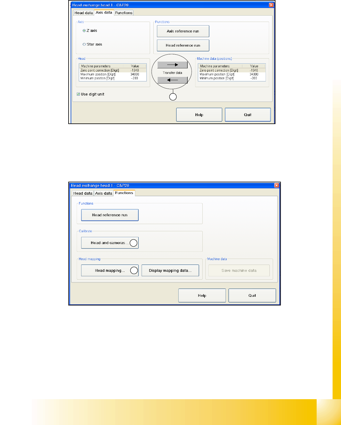
Axis data 11
Fig. 11.2 - 22 head modularity - axis data
(1) Here you can overwrite the Z- and star axis data from the head eprom to the machine data and
the other way round.
Function 11
Fig. 11.2 - 23 head modularity - function
(1) After the head was changed, it is possible to calibrate the changed head with help of the head
exchange menu. Of course it is also possible to calibrate the other heads with this function. Basicly
you can also calibrate the new head, and already installed heads in Sitest menu "Calibrate ma-
chine..." and then "All heads and cameras..."
(2) The same is valid here, see (1). After the head exchange you can directly do a head- map-
ping.You also find the function head- mapping in Sitest menu "Calibrate machine..." and then
"Head- Mapping".
1
1
2


Student Guide SIPLACE X
Edition 09/2005 Contents
1
Chapter
Table of Contents
12 Siplace X - Head Modularity . . . . . . . . . . . . . . . . . . . . . . . . . . . . . . . . . . . . . . . . . . 3
12.1 Head Modularity . . . . . . . . . . . . . . . . . . . . . . . . . . . . . . . . . . . . . . . . . . . . . . . . . . . . . . . . . . . . . . . . 3
12.1.1 Production requirements . . . . . . . . . . . . . . . . . . . . . . . . . . . . . . . . . . . . . . . . . . . . . . 4
12.1.2 Head exchange . . . . . . . . . . . . . . . . . . . . . . . . . . . . . . . . . . . . . . . . . . . . . . . . . . . . . 6
12.1.3 Menu Head exchange . . . . . . . . . . . . . . . . . . . . . . . . . . . . . . . . . . . . . . . . . . . . . . . . 7
12.1.4 Calibration . . . . . . . . . . . . . . . . . . . . . . . . . . . . . . . . . . . . . . . . . . . . . . . . . . . . . . . . . 9
12.2 Head modularity C&P Head to Twin Head . . . . . . . . . . . . . . . . . . . . . . . . . . . . . . . . . . . . . . . . . . 10
12.3 Head modularity Twin Head to C&P Head . . . . . . . . . . . . . . . . . . . . . . . . . . . . . . . . . . . . . . . . . . 11
12.4 Head modularity C&P 6/12 to C&P 20 Head . . . . . . . . . . . . . . . . . . . . . . . . . . . . . . . . . . . . . . . . 12
12.5 Preperation head plate . . . . . . . . . . . . . . . . . . . . . . . . . . . . . . . . . . . . . . . . . . . . . . . . . . . . . . . . . 13
12.5.1 C&P 6/12 head . . . . . . . . . . . . . . . . . . . . . . . . . . . . . . . . . . . . . . . . . . . . . . . . . . . . 13
12.5.2 C&P 20 head . . . . . . . . . . . . . . . . . . . . . . . . . . . . . . . . . . . . . . . . . . . . . . . . . . . . . . 14
12.5.3 Twin Head . . . . . . . . . . . . . . . . . . . . . . . . . . . . . . . . . . . . . . . . . . . . . . . . . . . . . . . . 15
12.6 Pressure air connector for the placement heads . . . . . . . . . . . . . . . . . . . . . . . . . . . . . . . . . . . . 16
12.7 Slots in the Axis unit . . . . . . . . . . . . . . . . . . . . . . . . . . . . . . . . . . . . . . . . . . . . . . . . . . . . . . . . . . . 18
12.7.1 Position of the Servosamplifier C&P 6/12 head . . . . . . . . . . . . . . . . . . . . . . . . . . . 18
12.7.2 Position of the Servosamplifier C&P 20 head . . . . . . . . . . . . . . . . . . . . . . . . . . . . 19
12.7.3 Position der Servos für Twin Head . . . . . . . . . . . . . . . . . . . . . . . . . . . . . . . . . . . . . 20
12.8 Connectors on the Hotlink Board (Computer unit). . . . . . . . . . . . . . . . . . . . . . . . . . . . . . . . . . . 21