SiplaceX4_en.pdf - 第142页
1 - 72 S tudent Guide SIPLACE X 3 Communication and Control Edition 09/2005 72 (4) Press "Send". (5) Command appears in the Netzwork window again and an answer (A cknowledge) will be send Ack b2 00 01 00 00 00 …
1 - 71
Student Guide SIPLACE X
Edition 09/2005 3 Communication and Control
71
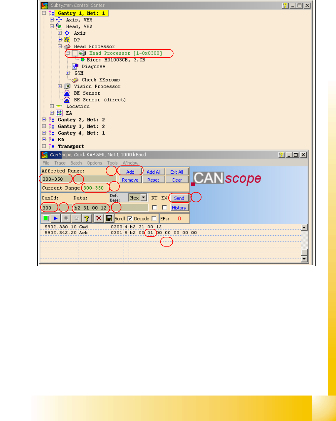
Fig. 3.6 - 13 Read the board type ID Head interface
(1) Reduce the range of CAN ID‘s.
- Write under "Affected Range" a small area of CAN ID‘s, to reduce the counter of CAN Bus
commands which appears in the network window.
- Confirm with "Add"
- The CAN ID Range will be show under "Current Range".
(2) Write the "Can ID" in the field "CanId".
(3) Write under "Data" the CAN Command.
e.g.. b2 31 00 120 b2 --> read EEPROM
31 --> read from headinterface
12 --> memory place in the memory (hex).
1a
1b
1c
2
3
4
5
1 - 72
Student Guide SIPLACE X
3 Communication and Control Edition 09/2005
72
(4) Press "Send".
(5) Command appears in the Netzwork window again and an answer (Acknowledge) will be send
Ack b2 00 01 00 00 00 00 00 --> the memory place 12 is 01 = Board type ID Head interface.
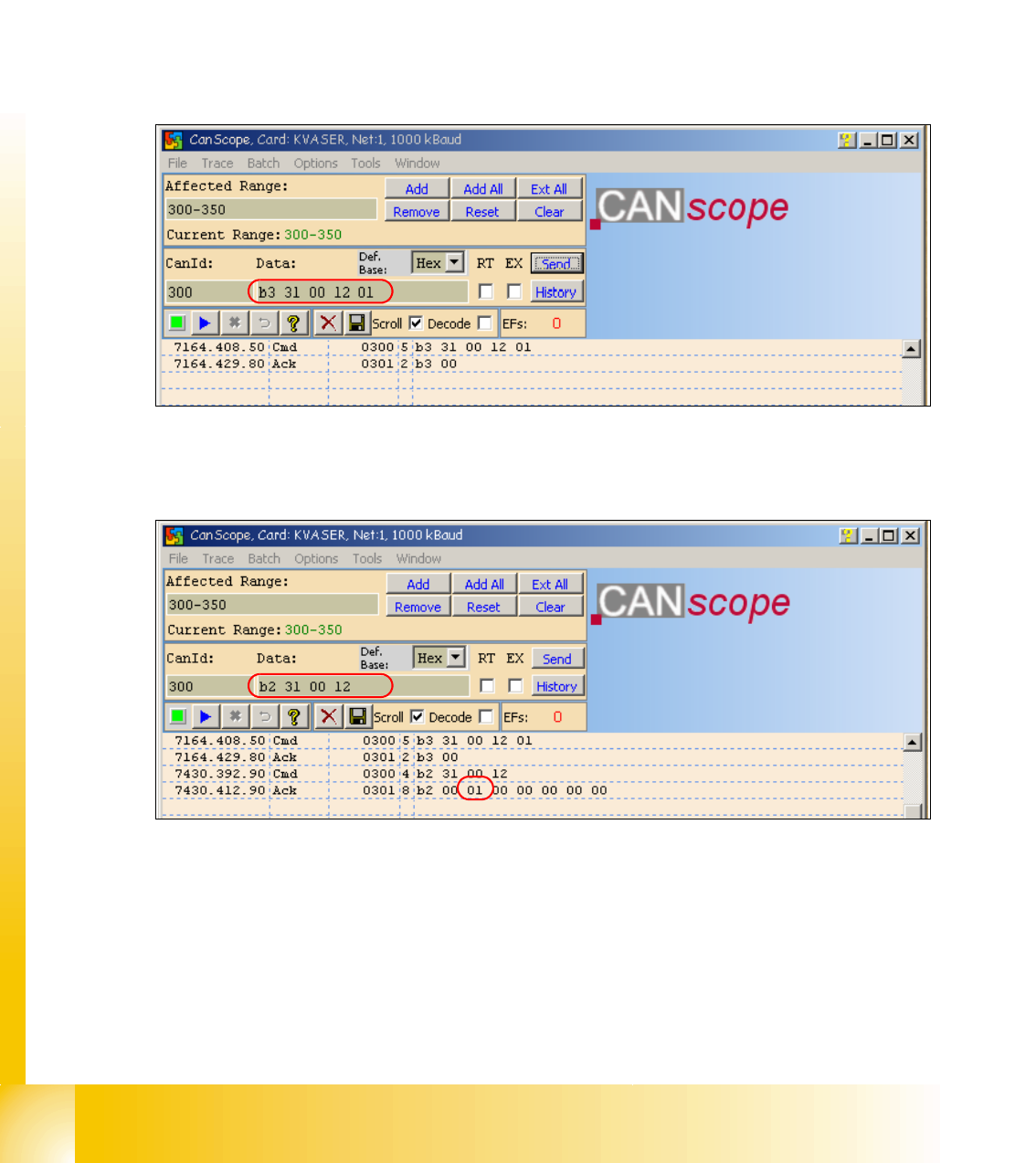
(6) Write the correct board type ID with command b3 31 00 12 01
b3 --> Write in the EEPROM
31 --> Head interface
12 --> memory place in the EEPROM
01 --> board type ID for the head interface
Acknowledege: b3 00 command OK
Fig. 3.6 - 14 CAN Command board type ID to write in the head interface
(7) Check the board type ID after you written the ID in the EEPROM
Fig. 3.6 - 15 Check the written board type ID
– Download the applications software on the TQM module.
– After the download the TQM module should running without error messages.

1 - 73
Student Guide SIPLACE X
Edition 09/2005 3 Communication and Control
73
3.6.3 Troubleshooting, if are missing two board type ID‘s
In this case, that two ID‘s are missing and the machine (TQM module) is not started can you use
standard CAN ID‘s for the TQM module on the head processor (see 3.6.2.1 Note).
3.6.4 CAN commands to read and write the board type ID‘s
Read out the board type ID from the EEPROM:
( e.g. Gantry 1 CAN ID 300 with C&P20)
CAN ID: 300 command: B2
31 00 12 read headinterface
CAN ID: 300 Acknowledge: B2 00 01 00 00 00 00 00 -->ID 01
CAN ID: 300 command: B2
32 00 12 read headadapter
CAN ID: 300 Acknowledge: B2 00 22 00 00 00 00 00 --> ID 22
CAN ID: 300 command: B2
33 00 12 read intermediate distributor
CAN ID: 300 Acknowledge: B2 00 30 00 00 00 00 00 --> ID 30
CAN ID: 300 command: B2
34 00 12 read vacuumgenerator digital
CAN ID: 300 Acknowledge: B2 00 00 00 01 00 00 00 --> ID 00 not defined
(memory place 14 = device number 01 for vacuumgenerator digital)
CAN ID: 300 command: B2
35 00 12 read vacuumsensor holding circuit
CAN ID: 300 Acknowledge: B2 00 31 00 00 00 00 00 --> ID 31
e.g. Gantry 1 Vision Board:
CAN ID: 180 command: B2
11 00 12 read Vision Board
CAN ID: 180 Acknowledge: B2 00 11 00 00 00 00 00 --> ID 11
e.g. Gantry 3 Vision Board stationary:
CAN ID: 150 command: B2
11 00 12 read Vision Board stationary
CAN ID: 150 Acknowledge: B2 00 12 00 00 00 00 00--> ID 12
e.g. Gantry 3 vacuumgenerator (analog) Twin Head:
CAN ID: 180 command: B2
36 00 12 read vacuum generator analog
CAN ID: 180 Acknowledge: B2 00 00 00 02 00 00 00 --> ID 00 not defined
(memory place 14 = device number 02 for vacuumgenerator analog)
When the TQM module on the head interface, so you can use the command 36, if the TQM mo-
dule directly on the twin head (main board, C600) so you have to use the command 22.