SiplaceX4_en.pdf - 第50页
1 - 26 S tudent Guide SIPLACE X 2 Overview Edition 09/2005 26 2.2.8 Construction of the Y -axis 2 Fig. 2.2 - 14 Construction of Y -axis Key The Y -axis consists of the following main modules: The Y-axis is driven by a li…

1 - 25
Student Guide SIPLACE X
Edition 09/2005 2 Overview
25
– The basic gantry is available in two versions. This is taken into account in the machine config-
uration! (SW 505)
– The Siplace X gantries has a metal strip for the travel range proximity switch in area (9).(Name
of the gantry version is CFK 04)
– The HF series gantries has a metal strip for the travel range proximity switch in area
(9a).(Name of the gantry version is CFK 02)
– New HF machine (which are signed with an " A "on the frame) have the gantry version CFK 04.
– The Siplace X gantries has a metal strip for the travel range proximity switch in area (9) and a
new trailing cable, which you can recognize with two additional pneumatic tubes on the right
side from the trailing cable. Name of the gantry version is CFK 06)
The following modules are installed on the head mount (2):
– PCB camera (6)
– Head boards (7) (head interface, head adapter)
– Incremental encoder
– Collect&Place head or twin head
The gantry arm (pos. 1 in fig. 2.2 - 13
) is made of carbon fiber material. This technology gives the
gantry arm high rigidity at minimum weight. The X-axis is driven by a linear motor. The secondary
part of the drive consists of a permanent magnet and is fixed to the gantry arm, while the primary
part is screwed to the head mount. The head mount is designed to fit all head types, which again
shows the great flexibility of SIPLACE machines.
2.2.7.1 X-Axis Technical Data
2
Drive direct, linear drive
Max. speed 2.5 m/sec
Travel range 471 mm
Mechanical travel range 480 mm
Measurement system Linear incremental encoder
Length of linear incremental encoder 520 mm
Resolution 1 µm
1 - 26
Student Guide SIPLACE X
2 Overview Edition 09/2005
26
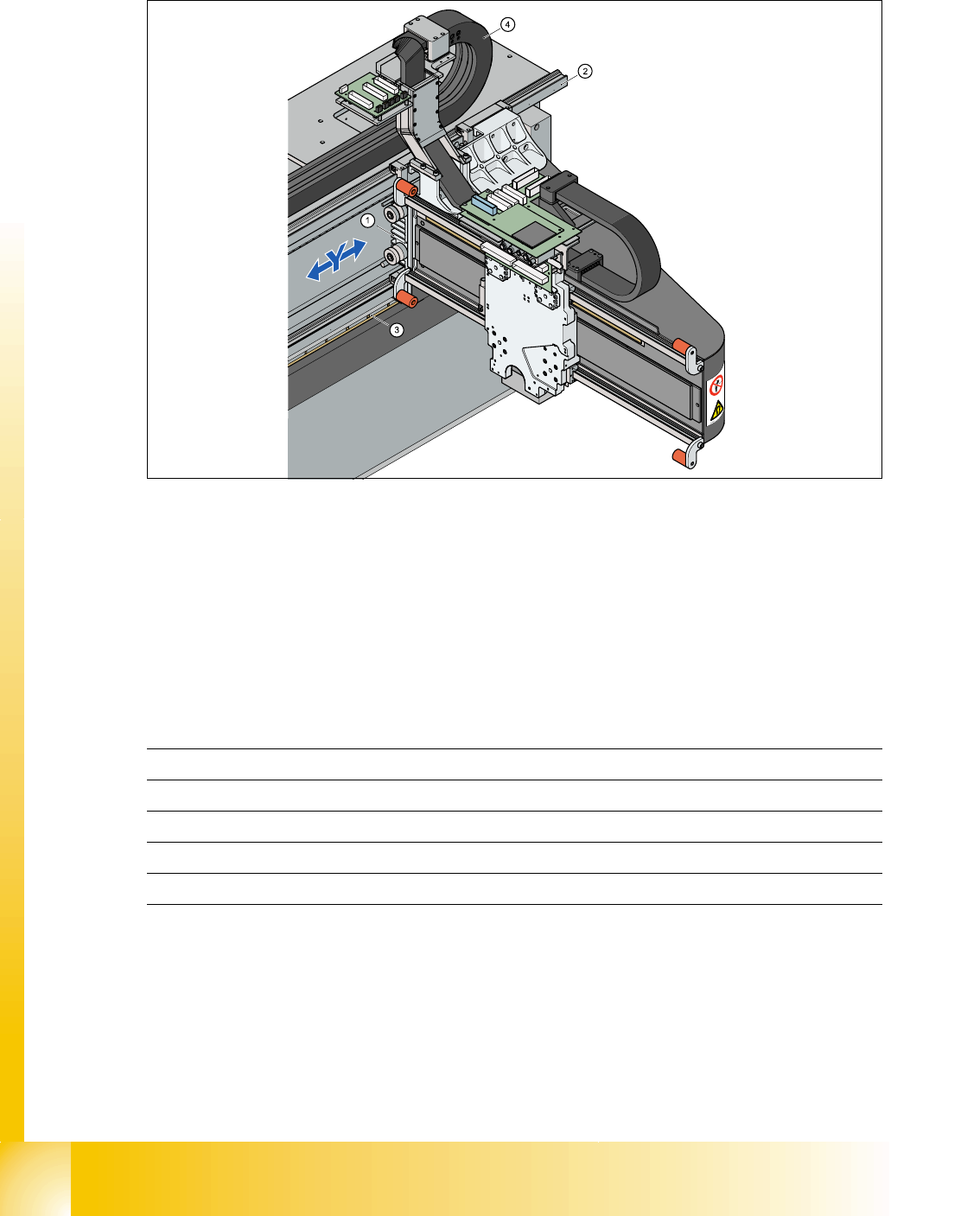
2.2.8 Construction of the Y-axis
2
Fig. 2.2 - 14 Construction of Y-axis
Key The Y-axis consists of the following main modules:
The Y-axis is driven by a linear motor. The secondary part of the drive consists of a permanent
magnet and is fixed to the machine frame. The primary part is screwed to the gantry arm (X-axis).
Y-axis technical data 2
(1) Linear drive permanent magnet (2) Linear incremental encoder
(3) Linear guide (4) Y-axis trailing cable
Drive direct, linear drive
Max. speed 2,5 m/sec.
Gantry travel range 1430 mm
Length incremental encoder 1850mm
Resolution 1 µm
1 - 27
Student Guide SIPLACE X
Edition 09/2005 2 Overview
27
2.2.9 Siplace Vision
The new, digital Siplace Vision system helps satisfy customer demands for greater speed, flexibil-
ity and robustness
Advantages of the digital Vision system:
– Robust and fast calculation algorithms
– Flexible measurement procedures
– Self-learning graphical user interface
– Supports geometrical description of components at the machine.
– State-of-the-art digital camera hardware
– Homogenous illumination of camera visual field and components
Each C&P head has its own digital component camera. For twin heads, a stationary camera is
installed in the machine.
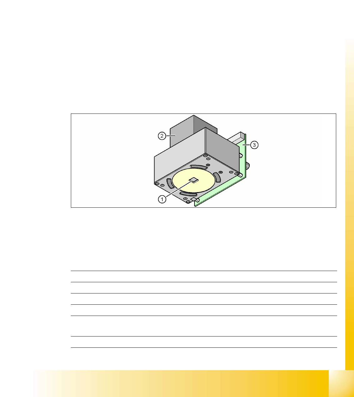
2.2.9.1 Digital PCB Camera (Multicolor)
2
Fig. 2.2 - 15 PCB camera under the gantry (X-axis)
(1) Camera optics
(2) Camera amplifier
(3) Illumination control for blue, infrared and white LEDs in the various illumination levels
Technical data 2
2
PCB fiducials max. 3 per placement program
Field of view (FOV) 5.7 mm x 5.7 mm
Illumination type from above
Resolution 9.8µm/pixels
Fiducial size 0.3 to 2.5 mm (up to 3.0mm, depending on PCB trans-
port tolerance.)
Camera type .sst 24.sst