SiplaceX4_en.pdf - 第63页
1 - 39 S tudent Guide SIPLACE X Edition 09/2005 2 Overview 39 2.2.1 1.2 Nozzle Changer for T win Head Siplace X machines with twin he ads are alwa ys equipped with a no zzle changer , which is installed in sector 3 or 1.…
1 - 38
Student Guide SIPLACE X
2 Overview Edition 09/2005
38
2.2.11 Twin Head
2.2.11.1 Description
The twin head consists of two identical P&P heads which work according to the pick&place prin-
ciple.The second P&P head is mounted on the gantry at an angle of 180 degrees. Two compo-
nents (one from each P&P head) can be picked up in succession from the feeder module and
optically centered with the help of the camera. On the way to the placement position, the compo-
nents are rotated into the correct position. They are then carefully and precisely positioned onto
the PCB with the help of controlled air kiss and a predefined force.
Type 5xx nozzles are used for the twin head. Type 4xx nozzles from the pick&place head and type
8xx and 9xx nozzles from the collect&place heads can be used with an adapter.
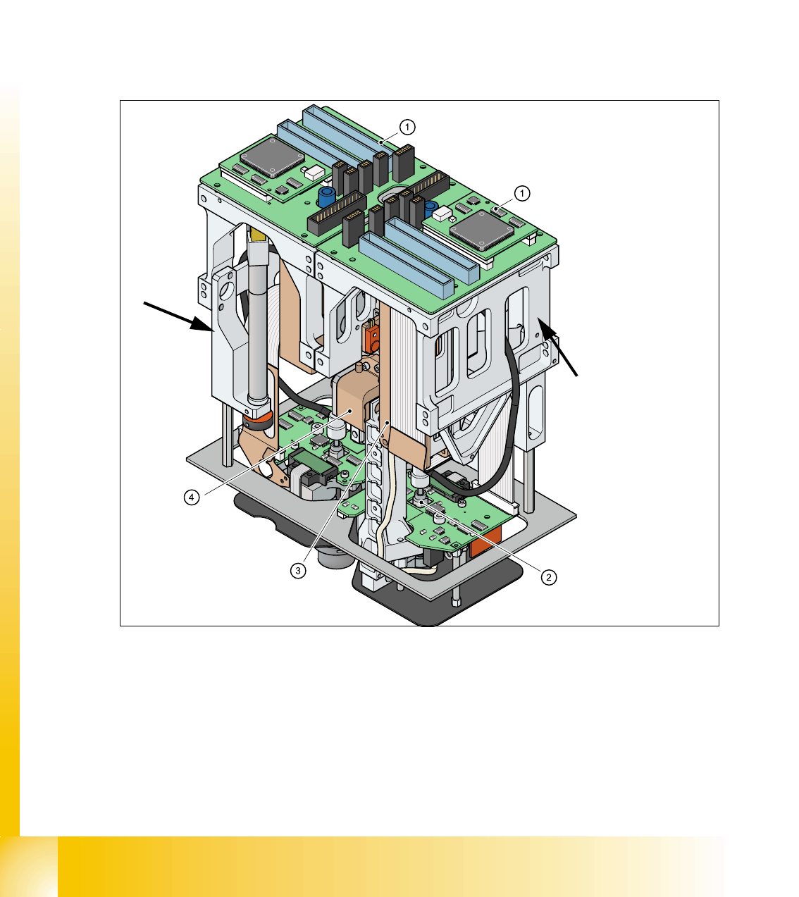
Fig. 2.2 - 25 Twin head
1. Main board on respective module (1 or 2)
2. D-axis
3. Z-axis linear motor
4. Z-axis incremental measurement system
Module 2, at an angle o
f
180 °
to module 1.
Module1
1 - 39
Student Guide SIPLACE X
Edition 09/2005 2 Overview
39
2.2.11.2 Nozzle Changer for Twin Head
Siplace X machines with twin heads are always equipped with a nozzle changer, which is installed
in sector 3 or 1.
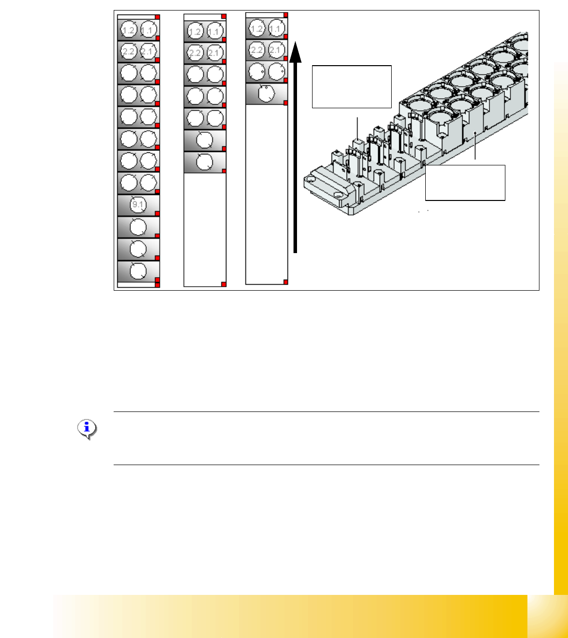
The nozzle changer for a twin head consists of the standard module with 3 garages, each with two
nozzles and one garage for a special nozzle (see Fig. 2.2 - 26).
Fig. 2.2 - 26 Nozzle changer for twin head
1. Standard nozzle changer
2. Extended nozzle changer
3. Complete nozzle changer
Note:
The configurations mentioned above can be changed as required and individual magazines for
standard and special nozzles can be added.
Magazin for 1
special nozzle
Magazin for 2
standard nozzle
Direction of trans-
port
1 - 40
Student Guide SIPLACE X
2 Overview Edition 09/2005
40
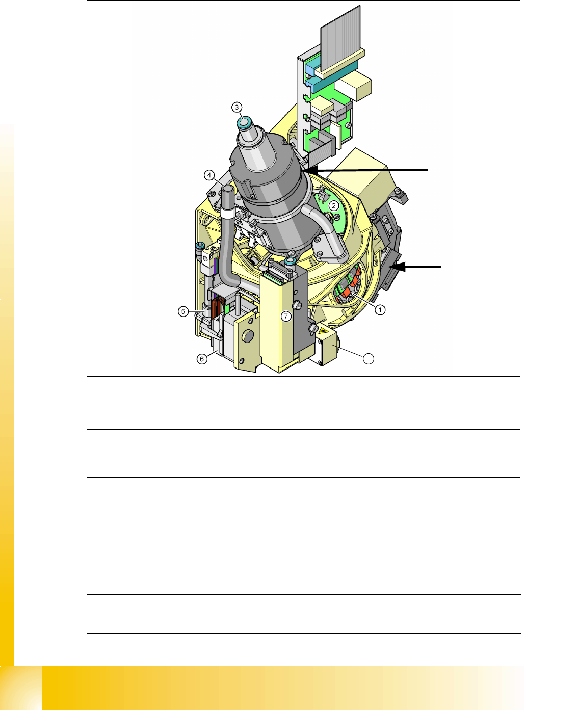
2.2.12 C&P20 Head
C&P20 head Key: 2
Technical data 2
2
Star motor
8
Component
camera
(1) Star with 20 segments (DP drives) (2) "Vacuum sensor for hold circuit board
(3) Compressed air supply for hold, pickup
and placement circuits
(4) X-linear motor cooling system
(discharged air from pressure control valve
(5) Return cylinder for Z-axis (6) Z-linear motor with measurement system
(7) Pressure control valve for pickup and
placement circuits
(8) Component sensor
Components 0402 to 2220, Melf, SOT, SOD
Maximum component size 6mm x 6mm x 4mm L/W/H
Minimum component size 0.2mmx 0.2mm
Maximum component weight 1g