SiplaceX4_en.pdf - 第57页
1 - 33 S tudent Guide SIPLACE X Edition 09/2005 2 Overview 33 2.2.10 C&P Head T ype DL M2 with 12/6 Segments Depending on the configuratio n, the Siplace X ma chines can be equipped with C&P 1 2 or 6-seg- ment he…
1 - 32
Student Guide SIPLACE X
2 Overview Edition 09/2005
32
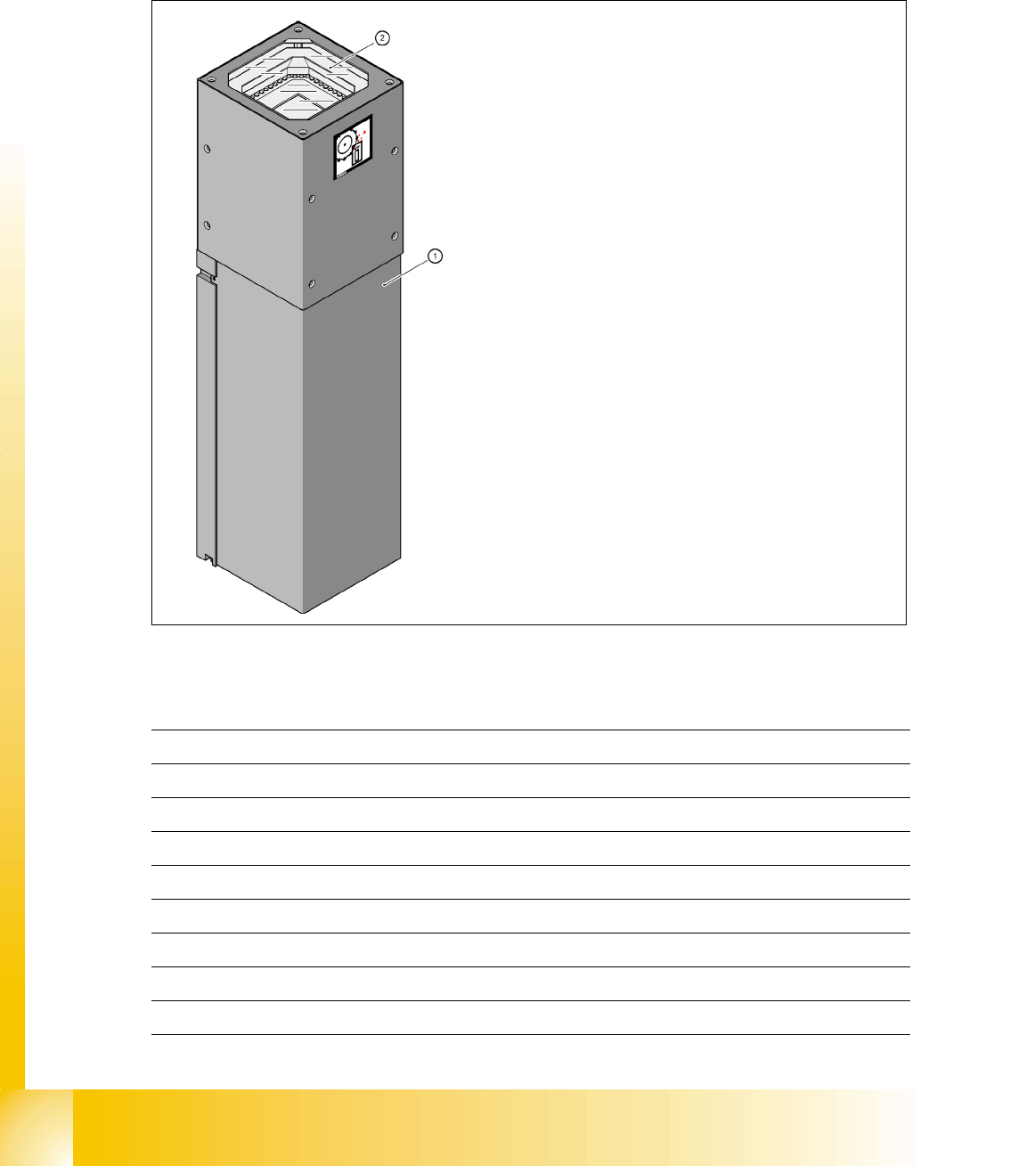
2.2.9.6 Flip - Chip (FC) Camera (Optional)
The flip chip camera or FC camera has greater resolution and is therefore ideal for all remaining
components in the SMD component spectrum.The structure of the FC camera is identical with that
of the IC camera, with its 6 illumination levels.
Fig. 2.2 - 19 FC camera
Technical data 2
2
(1) Camera housing with integrated camera and
camera amplifier
(2) Within the 6 illumination and optics levels
Component size 0.2mm x 0.2mm to 16 mm x 16 mm in single measurement mode
Components 01005, Flip Chip,µBGA, Bare Die‘s
Minimum lead pitch 0.25 mm
Minimum ball pitch 0.14 mm
Minimum ball diameter 0.08 mm
Field of view (FOV) 19 mm x 19 mm
Illumination type from above (6 levels programmable)
Resolution 16µm/pixels
Camera type .sst 25.sst
1 - 33
Student Guide SIPLACE X
Edition 09/2005 2 Overview
33
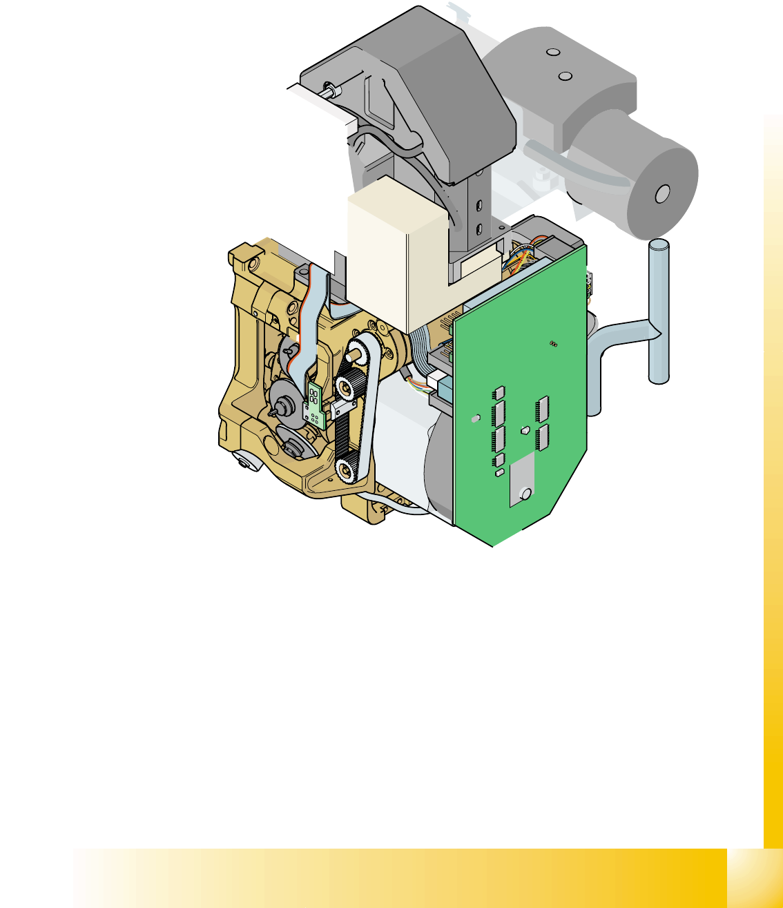
2.2.10 C&P Head Type DLM2 with 12/6 Segments
Depending on the configuration, the Siplace X machines can be equipped with C&P 12 or 6-seg-
ment heads of type DLM2.
Fig. 2.2 - 20 12-segment DLM 2 C&P head
(1) SP6_12 intermediate distribution board, digital
(2) Star motor
(3) Z-axis motor
(4) Stepping motor
(5) 24.5 x 24.5 component camera (SST.28)
(6) Vacuum system
Option: Digital camera SST.29 for the 12-segment C&P head and Component - sensor
(item no. 00118021-xx) for 0201 placement

1 - 34
Student Guide SIPLACE X
2 Overview Edition 09/2005
34
2.2.10.1 Steps When Picking Up and Placing Components
– A PCB moves into the placement area of the PCB conveyor and will be clamped.
– After the fiducial measurement, the C&P head picks up components from the feeder modules.
– The components are measured below the component camera and rotated into the correct
placement position (angle) in the DP station.
– The component is placed in star station 1.
2.2.10.2 Position and Function of the Individual Star Stations (see Fig. 2.2 - 21)
Star station 1 2
Pick-up cycle
The nozzle is lowered onto the component. The valve positioning unit opens the vacuum circuit to
the nozzle, the nozzle picks up the component and removes it from the feeder module.
Placement cycle
The nozzle, together with the component, is lowered onto the PCB that has been moved into
place. The valve positioning unit closes the vacuum channel to the nozzle. A short burst of com-
pressed air (air kiss) detaches the component from the nozzle and places it on the PCB.
Reject cycle
The valve positioning unit closes the vacuum channel to the nozzle. Defective components are
detached and discarded from the nozzle with a short burst of compressed air (air kiss).
Star station 3 (only used for the HS60 and S27 HM machines) 2
Note:
The HF- and Siplace X machines do not use star station 3 " reject component", as this function is
performed in star station 1.
Star station 7 2
The component is optically centered.
Star station 9 2
Pick-up cycle
The nozzle is rotated to the pick-up position.
Placement cycle
The component is rotated into the correct placement angle.