SiplaceX4_en.pdf - 第212页
1 - 18 S tudent Guide SIPLACE X 5 Gantry Edition 09/2005 18 5.3.4 Anti crash board The anti crash board is in the respective Axis unit installed an d make an immediate stop of the main axes in the case of exceed the trav…
1 - 17
Student Guide SIPLACE X
Edition 09/2005 5 Gantry
17
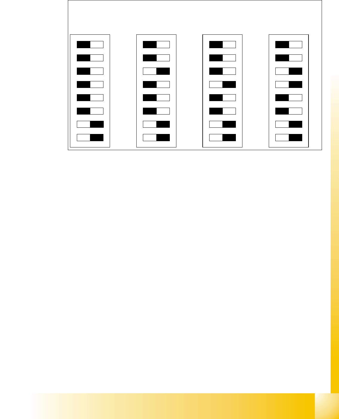
DIP Switches on the vision board 5
Legend
(1) Boot - CAN Processor 16 Bit at Sub board (2) Reset - CAN Processor 16 Bit at Sub board
(3) P0 - Gantry address switch 1 (4) P1 - Gantry address switch 2
(5) WPE - Write protect enable at the moment
OFF
(6) CAN R - CAN terminator
(7) Test 1 - CAN 1MBit/s ON (8) Test 0 - CAN group ON
DIP Switch
ON
78123456
ON
78123456
ON
78123456
ON
78123456
Gantry 1
Gantry 2
Gantry 3 Gantry 4
1 - 18
Student Guide SIPLACE X
5 Gantry Edition 09/2005
18
5.3.4 Anti crash board
The anti crash board is in the respective Axis unit installed and make an immediate stop of the
main axes in the case of exceed the travel range with over-high velocity.
Adjustments on the anti crash board are not necessary on the X2 machine!
With the X3/X4 machine the anti crash board with the distance sensor is activated between
Gantry 1/4 and 2/3 .( see Adjustment manual)
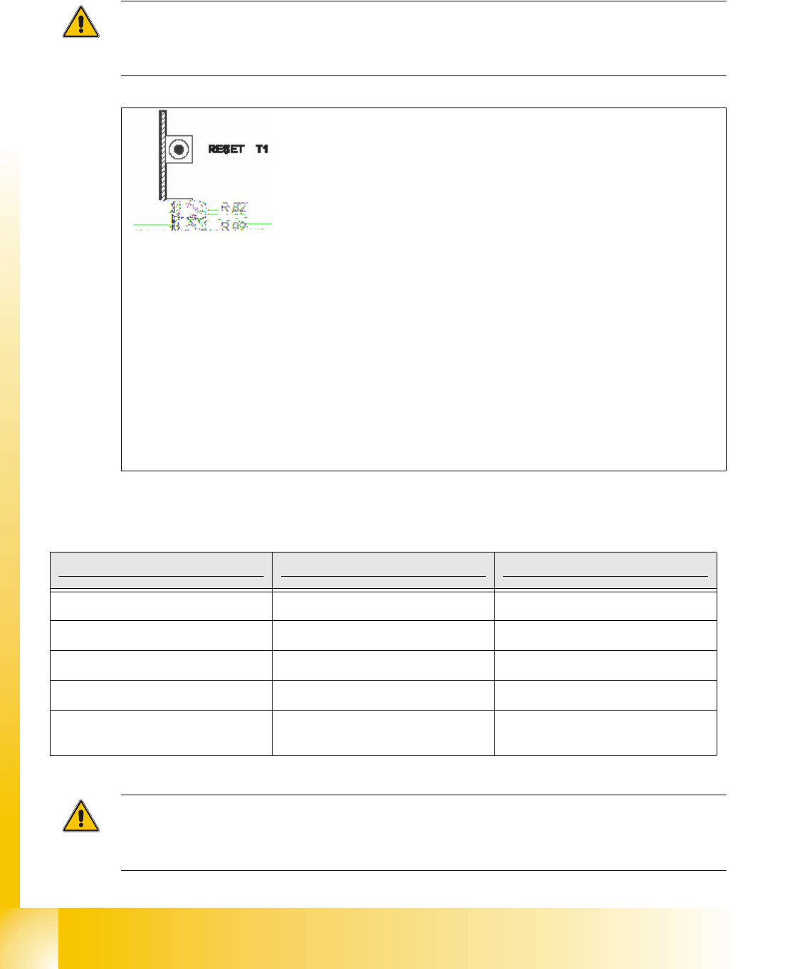
Fig. 5.3 - 7 Anti crash board
Description anti crash board Siplace X 5
Attention: Appears the anti crash board an error message(LED then OFF), please press the
emergency stop button on the machine at first and then the reset button at the anti crash board
for reset the error.
T 1-> Reset button
R82, R92 = Potentiometer
TP2 -> Speed-Signal
TP1 -> distance sensor Signal
LED X
I -> 1st X-axis "speed error"
LED X
II -> 2nd X-axis "speed error"
LED Y
I -> 1st Y-axis "speed error"
LED Y
II -> 2nd Y-axis "speed error"
LED DIS = Message: Distance sensor activated.
(not used on the X2 -machine)
Description Anticrash board in Axis unit PA 1 Anticrash board in Axis unit PA 2
LED XI X-axis Gantry 1 X-axis Gantry 2
LED XII X-axis Gantry 4 X-axis Gantry 3
LED YI Y-axis Gantry 1 Y-axis Gantry 2
LED YII Y-axis Gantry 4 Y-axis Gantry 3
LED DIS
depending on machinetype active/in-
activve
depending on machinetype active/in-
activve
Tab. 5.3 - 1 Description anti crash board

1 - 19
Student Guide SIPLACE X
Edition 09/2005 5 Gantry
19
5.3.5 Mechanical adjustment the incremental encoder
The incremental encoder on the X- and Y-Axis must be adjust of a distance of 0,4 mm +/- 0,1 mm
to the incremental scale.
Please Note:
For adjust the distance use a plastic feeler gauge of 0,4 mm.
After this adjustment of the incremental encoder you have to check the zero pulse and track sig-
nals (see chapter Tracksignals and Zeropulse).
Notes: