SiplaceX4_en.pdf - 第350页
1 - 34 S tudent Guide SIPLACE X 7 T win-Head Edition 09/2005 34 7.5.2 Position and assembly the nozzle changer 7.5.2.1 Position Fig. 7.5 - 2 Position nozzle changer "Standard configuration" here are on location…
1 - 33
Student Guide SIPLACE X
Edition 09/2005 7 Twin-Head
33
7.5 Nozzle changer
7.5.1 Nozzle changer for Twin- head
Die Siplace HF/HF3 and SIPLACE X machine will be delivered with a standard nozzle changer for
the twin head. This nozzle changer can hold up to 12 magazines. There are two types of magazine
available: standard magazines and magazines for special nozzles or grippers.
The nozzle changer may be installed depend on the configuration at location 1 and/or 3. The
nozzle changer consist of a standard modul with 3 nozzle holders two standard nozzles and one
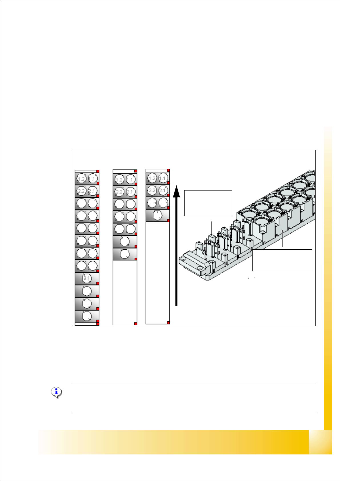
special nozzle or gripper. This configuration could be extended see Fig. 7.5 - 1.There are three
’Standard’ (504) magazine configurations.
Fig. 7.5 - 1 Nozzle changer configuration TWIN- head
(1) Standard-Nozzle changer
(2) Extended Nozzle changer
(3) Complete Nozzle changer
Please Note:
The magazines for standard, and special nozzles are freely configurable with the SW 505
or higher . 7
Transport direction
3
2
1
Magazine for
1 special nozzle
Magazine for 2
standard nozzles
1 - 34
Student Guide SIPLACE X
7 Twin-Head Edition 09/2005
34
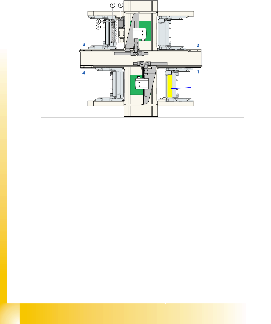
7.5.2 Position and assembly the nozzle changer
7.5.2.1 Position
Fig. 7.5 - 2 Position nozzle changer "Standard configuration" here are on location 3
Legend (The blue numbers show the feeder areas.)
(1) Nozzle changer no. garage 1 (2) Standard magazine set up
(3) Magazine for special nozzles or grippers (4) Component reject bin
Option TWIN on G1
nozzle changer space
1 - 35
Student Guide SIPLACE X
Edition 09/2005 7 Twin-Head
35
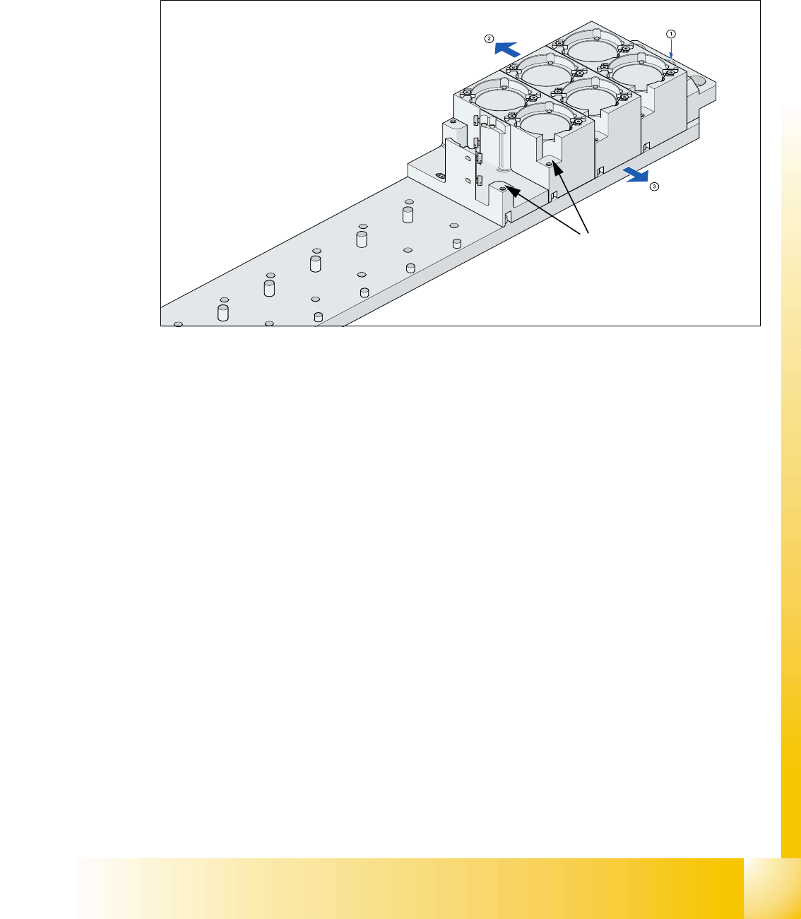
7.5.2.2 Assembly nozzle changer magazine
The nozzle changer together with the empty tape duct is fixed on the component docking unit. The
magazines are seated on a common support. They are centered with two parallel pins and fixed
in place with two countersunk screws.
Fig. 7.5 - 3 Assembly magazine
Legend
➠ Align the nozzle changer so that the marking hole (item 1) is on the left, as viewed by the op-
erator at component table side.
(1) Fiducial for optical X/Y position recognition
of the magazine carrier.
(2) Arrow pointing to component table
(3) Arrow pointing toward the PCB conveyor (4) Fiducial for optical X/Y position recognition
of the magazines.
(4)