SiplaceX4_en.pdf - 第381页
1 - 15 S tudent Guide SIPLACE X Edition 09/2005 8 Collect&Place-Head 20 15 8.1.4 Pressure air supply DLM 2 C&P head Fig. 8.1 - 3 Pressure air connectors C&P head 8.1.4.1 Holding circuit (1) Pressure air conne…
1 - 14
Student Guide SIPLACE X
8 Collect&Place-Head 20 Edition 09/2005
14
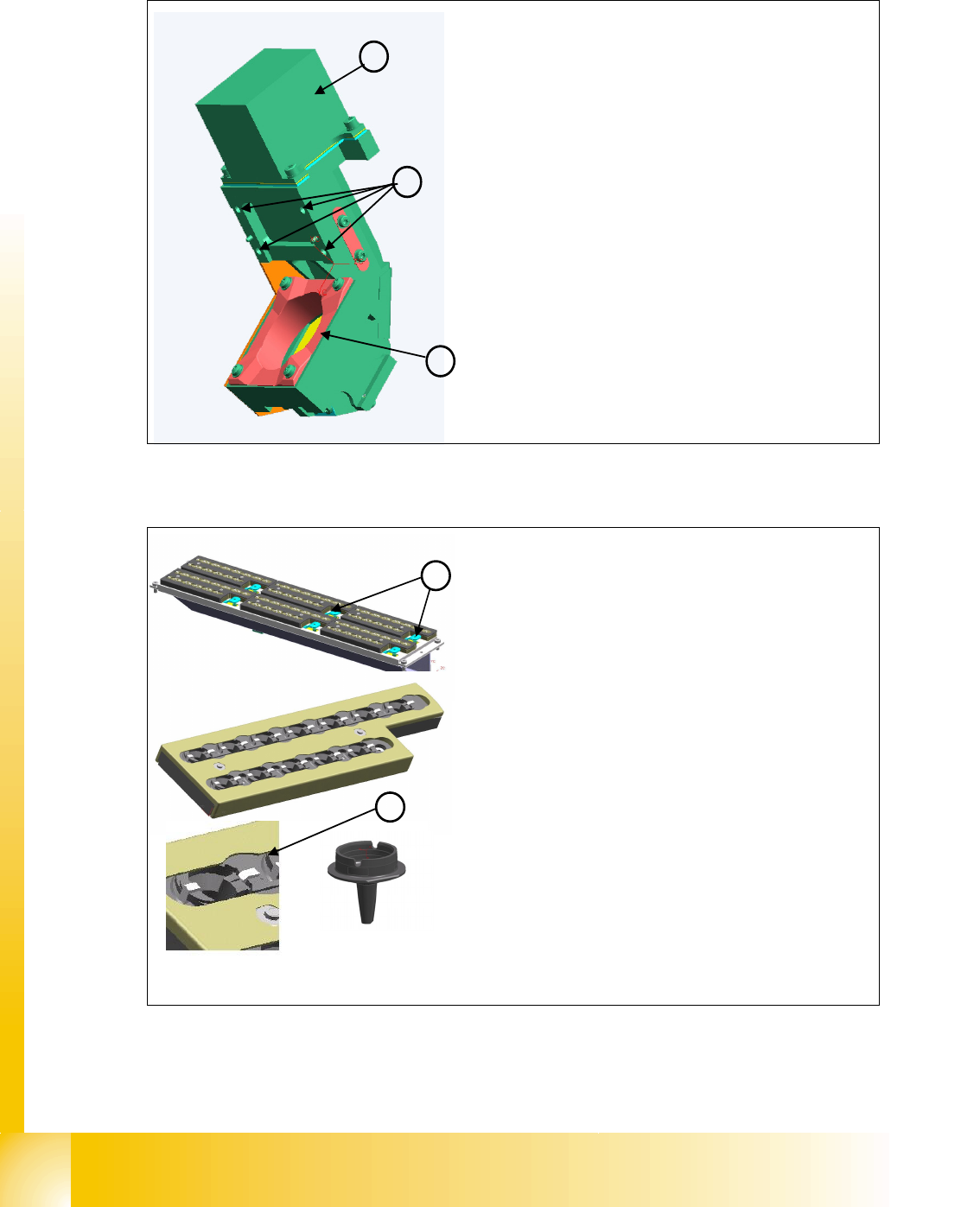
8.1.3.8 Component camera
8.1.3.9 Nozzle Changer
1
2
3
Component Camera (Type 23 digital)
The component camera is fixed to the C&P20 head
with 4 screws and can be replaced during service work.
Five levels are available for illuminating the compo-
nents.
Visual field: 8.2 x 8.2 mm
Resolution: 14.1 µm/pixels
Component spectrum 01005-2220 max. 6x6mm, Bare
Dies, Flip Chip
Component Camera Details
Optical system (1)
Fixture (2) to housing
Camera amplifier
(3)
1
2
Nozzle Changer (optional)
The nozzle changer has 6 magazines, each with 12
nozzle garages for individual configuration.
A maximum of 2 nozzle changer charrier can be in-
stalled for each C&P 20 head.
If the nozzle changer is returned, the height of the noz-
zle changer needs to be checked with a calliper.
Each magazine is recognized via a micro switch and in-
dicated by a green LED.
The functions and calibration are identical with that of
nozzle changers for DLM heads.
Nozzle Changer Details
Push down openers (1) for magazines
Bracket
(2) to hold nozzle during return to garage
1 - 15
Student Guide SIPLACE X
Edition 09/2005 8 Collect&Place-Head 20
15
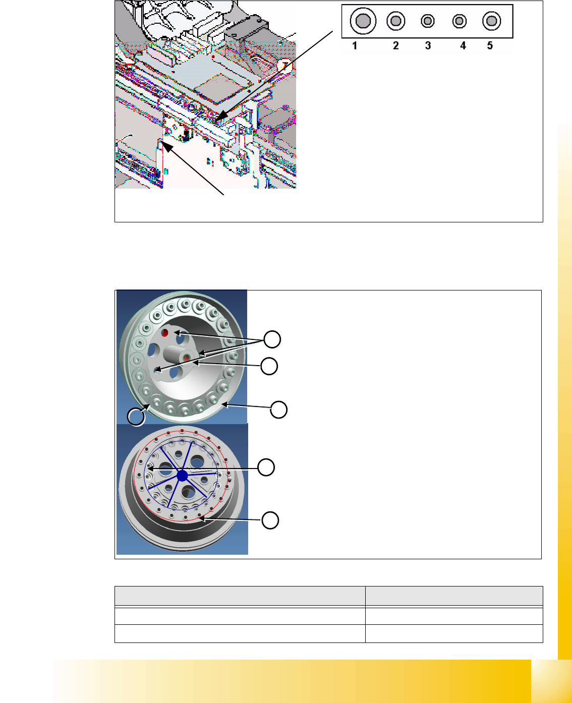
8.1.4 Pressure air supply DLM 2 C&P head
Fig. 8.1 - 3 Pressure air connectors C&P head
8.1.4.1 Holding circuit
(1) Pressure air connector for C&P-head Va-
cuum-holding circuit 4,7 bar Input pressure air
for the Placement head
(2) Pressure air connector for C&P-head Va-
cuum-pick up circuit with branching for the air
kiss supply 4,7 bar Input pressure air for the
Placement head
(3)-(5) Blind connector (Connector for Twin head)
Pressure air connector for cooling
X-Motor
Description Part No.
Venturi Block
-0X
O-Ring (6)
03011347-0X
1
1
2
2
3
3
4
4
6
6
5
5
Venturi Block
The venturi block consists of 20 small venturi nozzles
and is located behind the silencer.
Each venturi nozzle supplies one segment with vacuum
in the hold circuit.
If a segment is in the pickup/placement circuit, the hold
circuit vacuum is increased (for pickup) or eliminated
via air kiss (for placement).
Venturi Block Details
– Mounting (1) for star frame
– Mounting
(2) for silencer
– Venturi nozzle discharged air
(3) to the silencer
– Venturi nozzle vacuum outlet
(4) to the segments.
– Compressed air inlet
(5) to venturi nozzle The venturi
nozzle entrances have seals.
–O-ring
(6) between venturi block and silencer
1 - 16
Student Guide SIPLACE X
8 Collect&Place-Head 20 Edition 09/2005
16
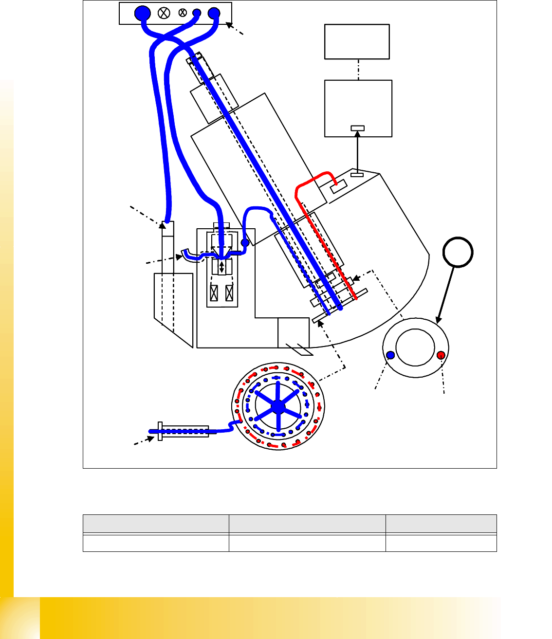
8.1.4.2 Overview Air kiss supply
Red (light grey): Vacuum
Blue (black): pressure air (Air kiss)
8
Fig. 8.1 - 4 General overview ot the function Air kiss
Position Description Part No.
1 Distributor disc
03008286-0X
Holding
circuit
Intermediate
board
Z-axis
B
B
A
Compressed
air distributor
(4.8-5.0bar)
MC
C
C
A
A
e.g. Segment 1
Pickup/
placement
circuit
Measurement of
vacuum/air kiss values is
performed in the
pressure control valve
CAN bus
1
Retract unit
Z-axis
Cooling system
X-motor
Holding
circuit
Intermediate
board
Z-axis
B
B
A
Compressed
air distributor
(4.8-5.0bar)
MC
C
C
A
A
e.g. Segment 1
Pickup/
placement
circuit
Measurement of
vacuum/air kiss values is
performed in the
pressure control valve
CAN bus
11
Retract unit
Z-axis
Cooling system
X-motor